Project update 11 of 21
Prototype Update
Hi all,
Happy new year!
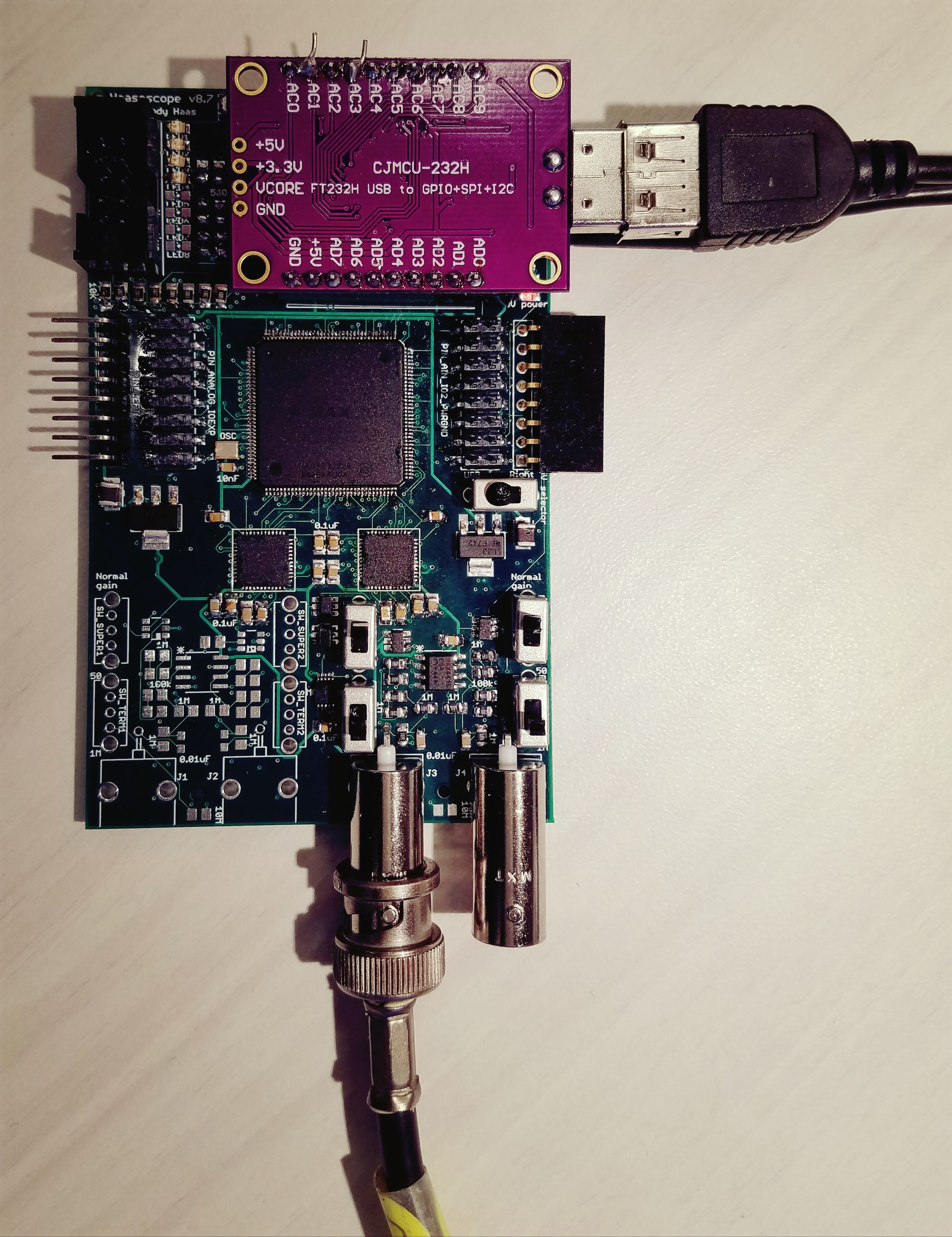
I’ve been in Mexico for 2 weeks, but upon return I assembled (well, channels 2+3 at least) the latest bare PCB from AllPCB.com that was waiting for me in the mail. And after a couple tweaks, I think I finally have a board ready for production! Here it is:
Now that I’m happy with it, I’ve ordered 4 final prototypes from MacroFab.com, fully assembled. They’ll arrive at the end of the month. Once I’ve tested them, I’ll make a few more minor tweaks, if needed, and then order 200 boards, which should arrive towards the end of February. So you should start getting your orders in early March! (Mugs will ship out now.)
Some new features:
- Even less noise! The analog parts (ADC, op-amp, etc.) are now powered from a separate voltage regulator, providing some needed isolation from the noisy digital (FPGA, etc.) current draws. I've also added extra low-pass filtering to the DAC offsets to the op-amp.
- The USB2 optional add-on board now fits better than ever, like they were meant to be together. (That's the purple board in the pic above.)
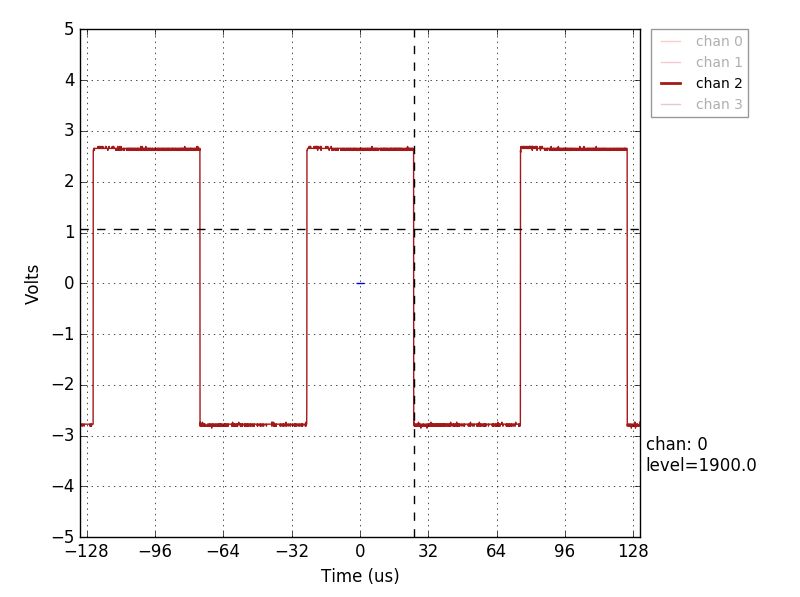
- Adjustable frequency compensation. What's that? Basically, it gives you two little knobs to turn on the board for each gain of each channel, that lets you match the gain at high frequency to that at low frequency. It makes a square wave square! (You have these on oscilloscope probes too.) If you want to know more about it, read below!
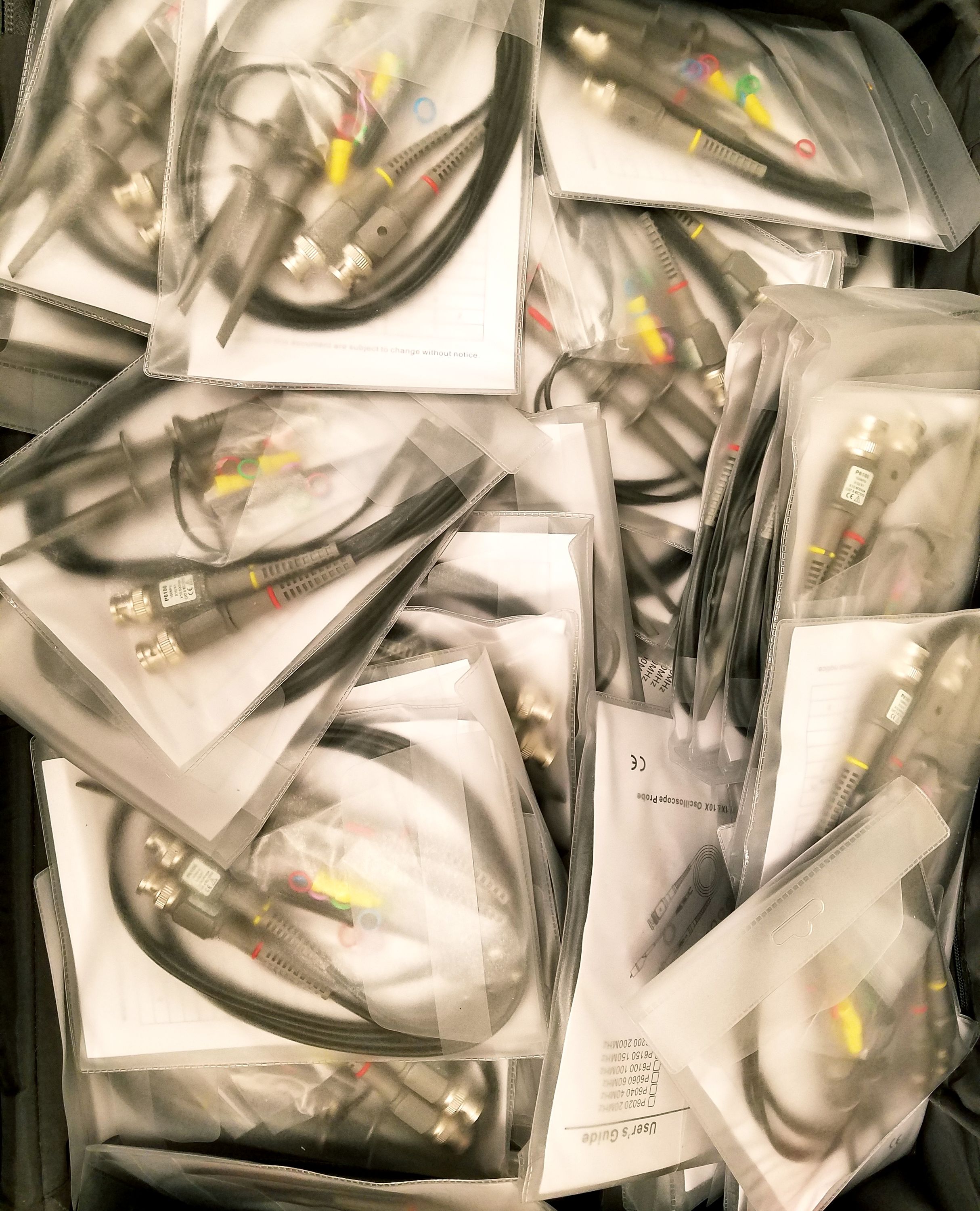
I’ve also received all the other parts that will go in the Haasoscope bundle, etc. Here’s what (some of) 400 oscilloscope probes looks like!
The Story of Compensation:
You may know about the basic op-amp negative feedback gain circuit:
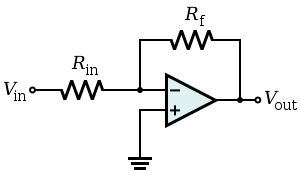
The gain is given by -R_f / R_in. However, when R_in is big (and for us it’s 1MOhm… you want high impedance in an oscilloscope, to not significantly affect (load) the signal you’re trying to measure!), there can be smaller impedances at large frequency. Remember than impedance for a capacitor is 1/wC, where w=2pi*f. At 1 MHz, even a "stray capacitance" of 1 pF gives an impedance of 1/2pi MOhm, or ~150k! And there’s stray capacitance everywhere, between any two wires, it’s unavoidable! The gain is then no longer controlled by R_f / R_in, it’s dominated by C_in / C_f !
So what do we do? The trick is to add some additional capacitance intentionally, that you can carefully control. So instead of C_in and C_f being stray capacitance, it’s a reasonably solid value. As long as C_in / C_f = R_f / R_in , the gain is always the same, at low or high frequency! Here’s a little more info about it: https://electrosome.com/compensated-attenuator/ . You may have noticed on your big old oscilloscope that the inputs are "1 MOhm, 13 pF", well, this is where that 13 pF comes from and why it’s there! (Also so 10x probes are easy to use/make… but that’s another story!)
For example, for "high" gain, we want a gain of 2. I use a 2MOhm R_f (actually 2 1MOhm resistors in series, to save $!), and R_in is 1 MOhm. Then I add an intentional capacitance of 10pF in parallel (C_in), so I want C_f to be 5pF. Great, done! Well, almost. There’s still about 1 pF of stray capacitance, so the ratio of C_in/C_f is not going to be exactly 2, unless you get lucky. You need to adjust the capacitance (within a few pF), to account for wherever that stray capacitance happens to be coming from. It can also change with temperature, humidity, component ages, etc.! So that’s what we do - we add little adjustable capacitors to the board, to let you fine-tune C_in/C_f, so the gain is constant vs. frequency. You just need a little tiny flat-head screwdriver (plastic, so you don’t add capacitance from your body while adjusting it!). I’ll tune them all before I ship it to you, but you may need to adjust it later. This is what it finally looks like (for all gains and all channels):