Project update 3 of 10
Design Evolution of the Programmable USB Hub
Today’s update is going to be a dive into the design progression and evolution of the Programmable USB Hub. Note, I didn’t start out with the aim of creating a product which smashes together a USB Hub, Power Supply, Development Board, and IO expander — my aim was simply to create a product which provided more monitoring and control of USB devices.
First, let’s start with a block diagram of a standard 4-Port USB Hub.
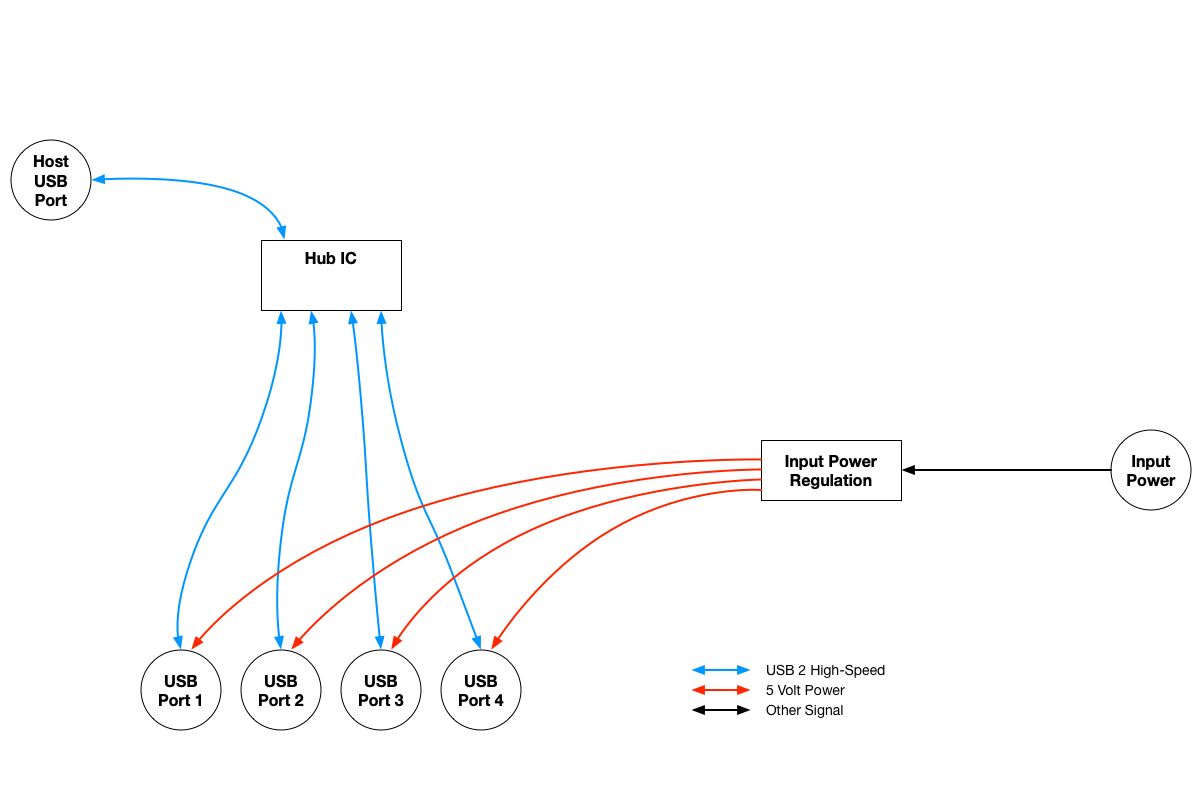
It’s straightforward: a USB Hub IC and some input power regulation, most commonly 12 volt to 5 volt & 500 mA available per-port.
This kind of design has no power isolation between the downstream ports — meaning that one misbehaving device (or cable) can cause a power fault which cascades and spreads to the other ports. It also cannot prevent a downstream device from drawing more power than the hub’s regulation is capable of.
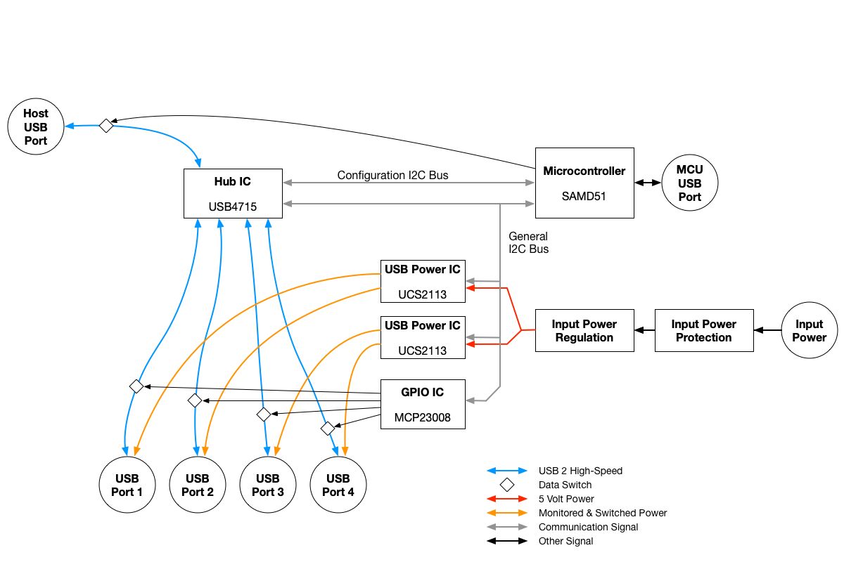
So, let’s resolve both of these issues by introducing per-port power protection ICs to the design. This design also includes power protection on the power input, which prevents excessive input voltage or reverse-power-polarity from causing permanent damage.
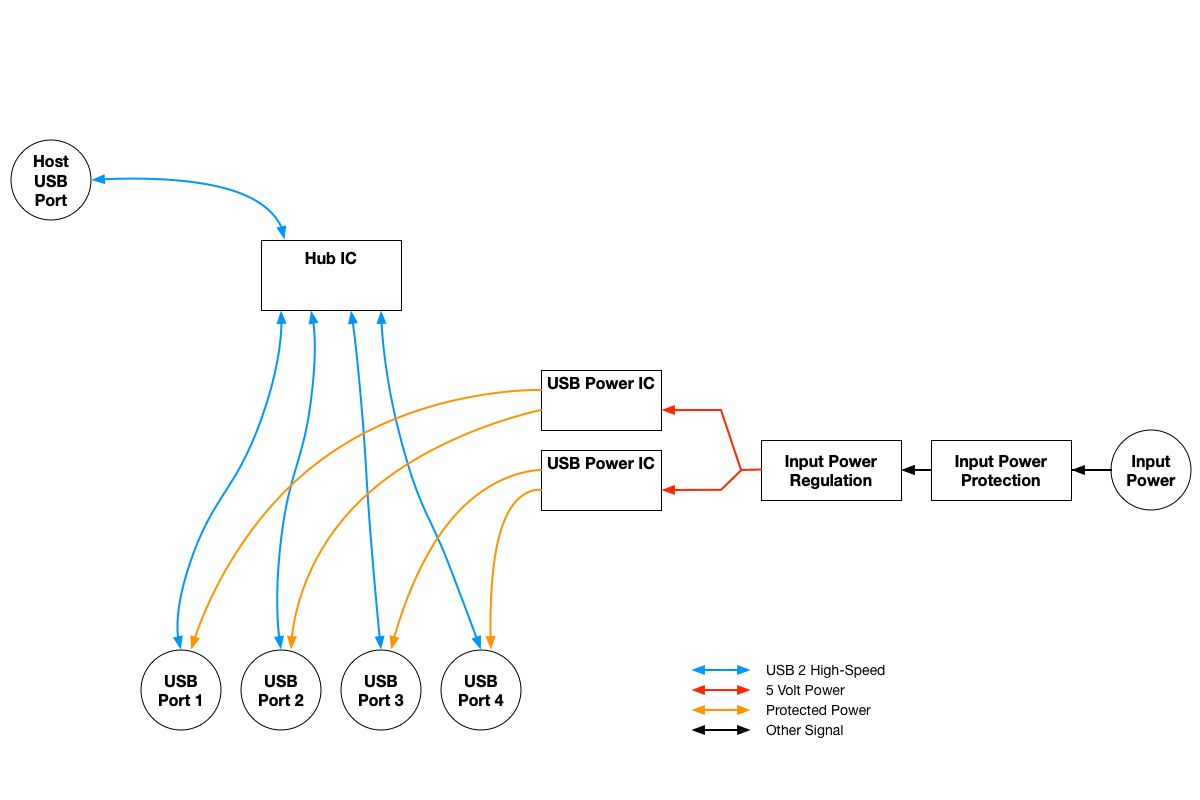
Now, the design is protected from upstream power faults (like voltage spikes), and downstream devices have isolated and protected power rails. But if a downstream device stops communicating with the Host, we don’t have any visibility as to why that has occurred. It could be the device drawing more current than allowed and the port-protection kicking in or it could be something else entirely - like software on the device crashed.
To help determine the cause of this sort of loss of communication (and potentially recover from it), it would be useful to have per-port power monitoring and per-port control, in addition to the per-port protection.
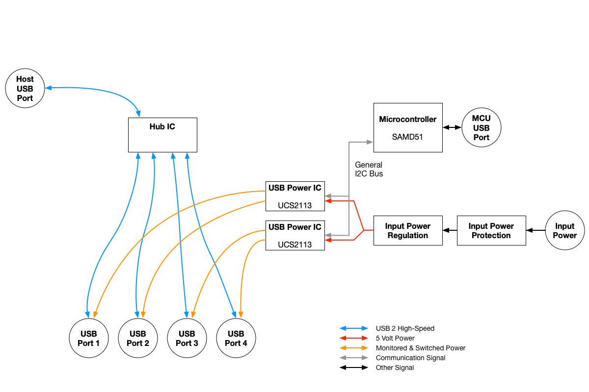
Microchip makes a part which is designed for exactly such an application, the UCS2113. This chip features:
- Per-port power control & current monitoring.
- Adjustable current limits and configurable fault handling.
- Fault alert pins, which can signal errors to the Hub IC.
- I2C-based communication and control interface.
The Hub now also features a SAMD51 MCU which controls and monitors the UCS2113 power management ICs over I2C. The MCU can therefore power-cycle downstream USB devices and report per-port power draw over its’ upstream USB 2 Full-Speed port.
The next step in making a more capable USB Hub is to extend this monitoring & control capability to the USB data pairs themselves. For example, if a downstream device is externally powered, instead of USB powered, we cannot reset it if communication is lost.
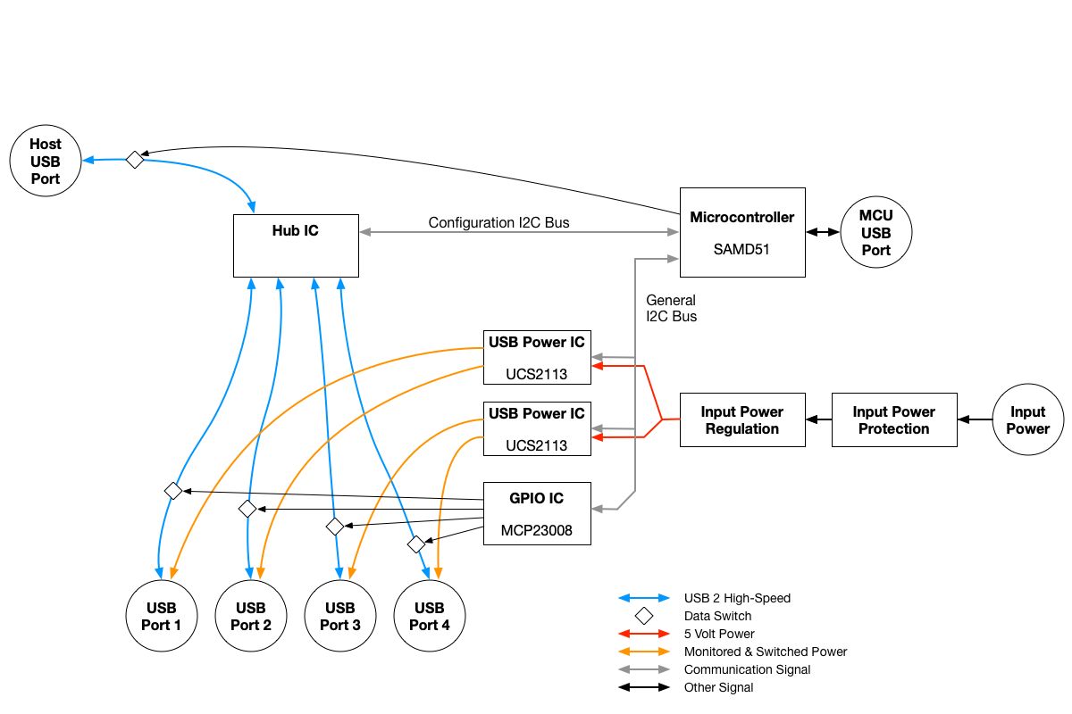
The MCU can now communicate with the Hub IC via I2C, to learn the negotiated USB speeds of attached devices. Unfortunately, there don’t seem to be USB Hub ICs which allow downstream ports to be dynamically enabled and disabled. Some Hub ICs allow ports to be permanently flagged as disabled (in case that port is not pinned out to a connector), but that sort of one-time configuration doesn’t aid us in resetting a downstream USB device.
Therefore, dedicated high-speed data switches have to be added to the design for each USB pair. The Programmable USB Hub uses a TS3USB31 USB2 High-Speed switch for each port. These ICs are crazy tiny - the 8 pin package is 1.5mm x 1.5mm.
Now we have a Hub where the following can be known:
- Downstream device connected speed
- Per-port current draw
and the following can be controlled:
- Per-port current limit
- Per-port power enabled or disabled
- Per-port data line connected or disconnected
all from the embedded MCU. But, wouldn’t it be great for this monitoring and control to be available to the upstream USB host too? It would indeed, and the USB4715 Hub Controller IC has a USB to I2C bridge built into it.
This I2C bridge allows the Upstream USB Host to communicate with all of the I2C devices inside the USB Hub, meaning the Host can monitor and control everything identically to the internal MCU. Now it’s a bit more clear why an I2C GPIO expander was used to control downstream data switches, instead of GPIO built into the MCU.
What’s missing now is feedback to the end-user about all of this useful internal hub state and configuration.
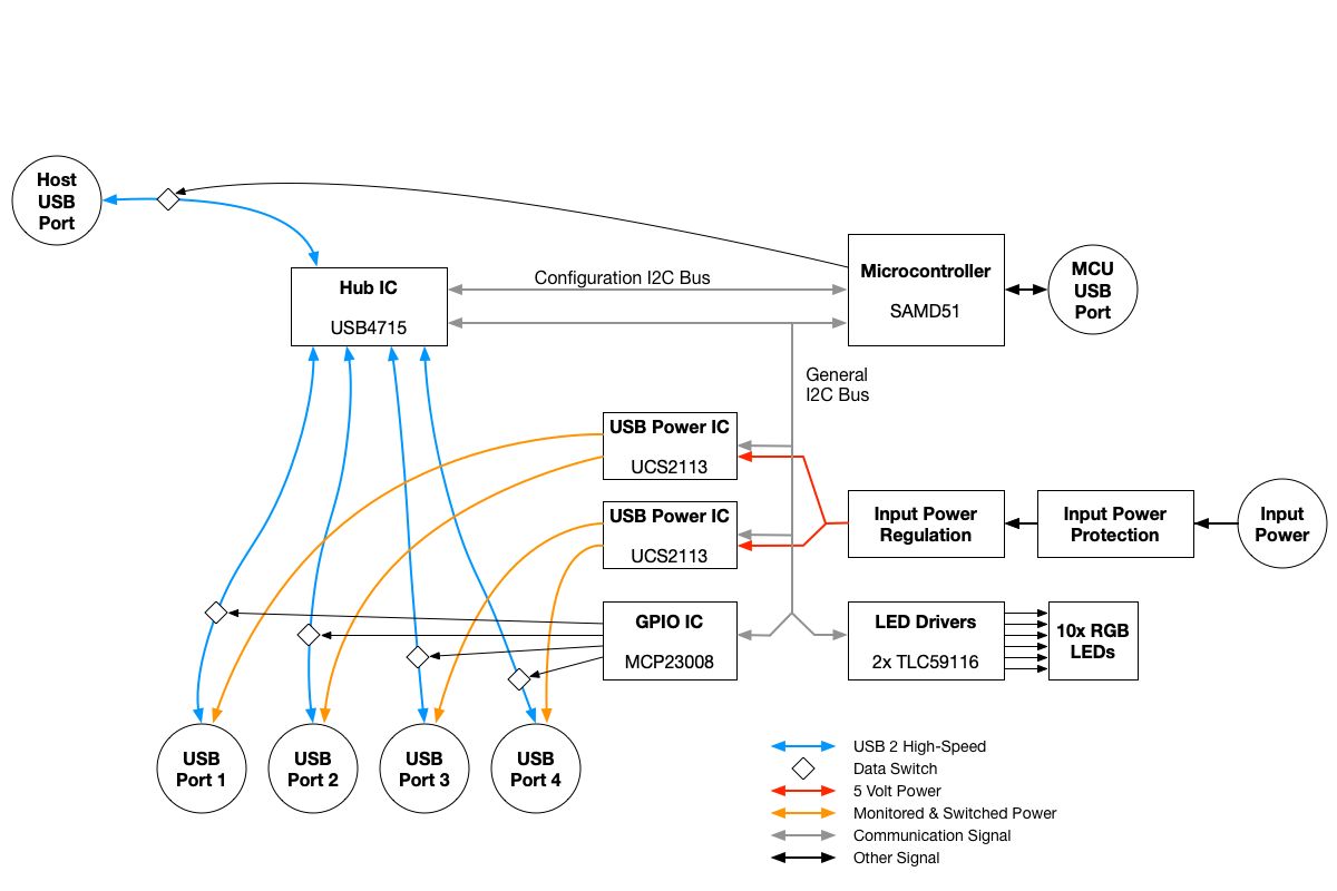
With the default firmware behavior, the 5x Data LEDs show per-port data state with the following meaning:
- White : High speed device detected
- Green : Full speed device detected
- Blue : Low speed device detected
- Off : No downstream device detected
- Orange : Port data lines internally disabled / disconnected
and the 5x Power LEDs show per-port power draw in blue, with higher port power displayed as a brighter blue. Ports which have power turned off are lit orange and any over-current condition is shown by lighting the LED red.
Lastly, the USB4715 Hub IC has some additional bridging capability and breaking those out inside and outside the Hub expands the flexibility of the Hub and allows the upstream host to easily communicate with and control embedded sensors and devices.
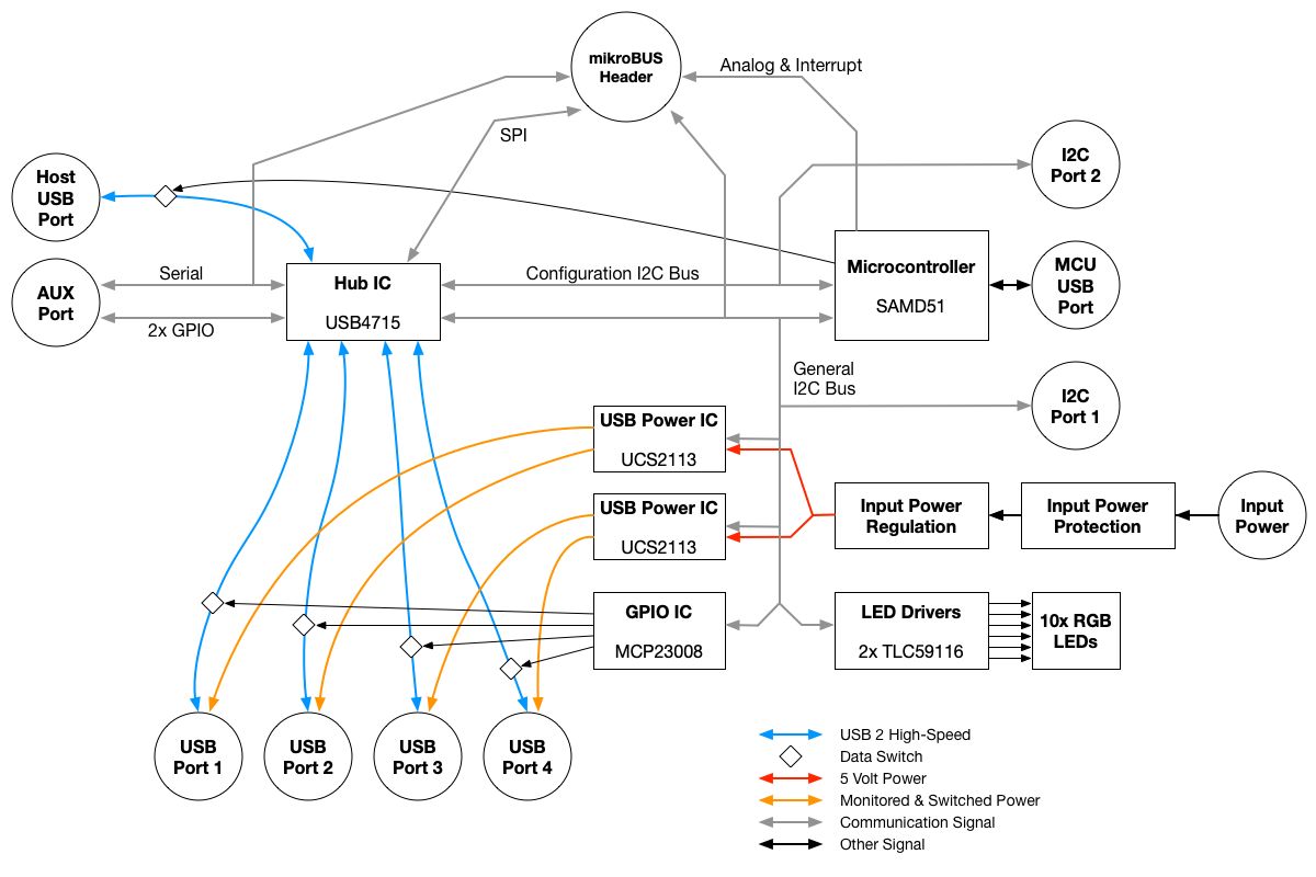
There you have it, the block-diagram of the Capable Robot Programmable USB Hub! There is a lot of flexibility and capability in this device! I hope you enjoyed learning about the design progression of the Hub and why particular components were selected for various functions.
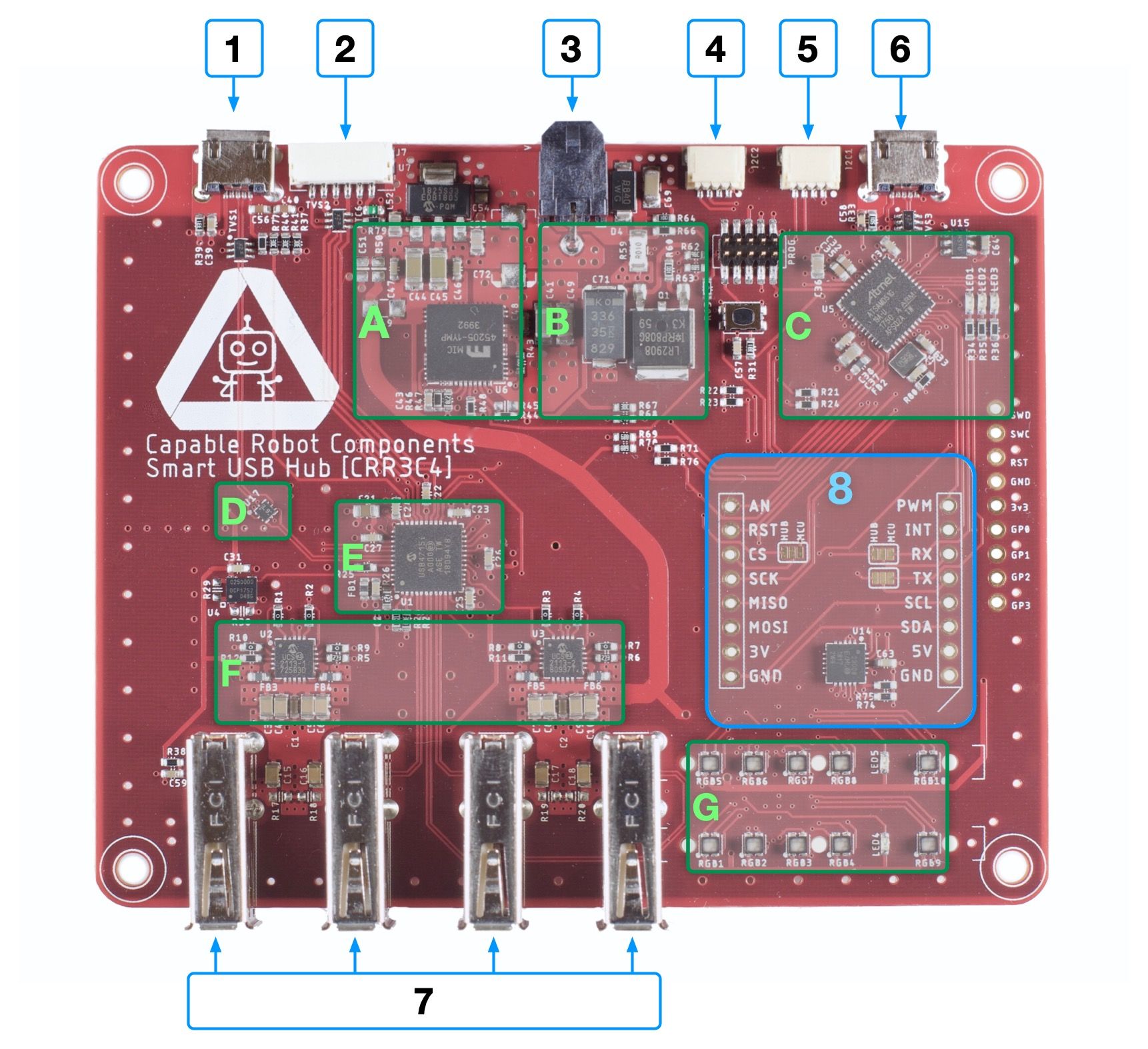
| Blue: Connectors & IO | Green: Functional areas of the board |
|---|---|
| 1. Upstream USB | A. 5V 6A Regulator |
| 2. USB UART & GPIO | B. Input Protection |
| 3. 12 V / 24 v DC In | C. Programmable Microcontroller |
| 4. USB Hub I2C | D. 1 of 5 USB Data Disconnects |
| 5. MCU I2C | E. USB Hub |
| 6. MCU USB | F. Downstream USB Power Protection & Switching |
| 7. 4x Downstream USB | G. RGB Status LEDs |
| 8. mikroBUS Header |