Project update 8 of 10
Production Update
With the campaign successful (woohoo!) and concluded, our efforts have now transitioned to preparing-for and starting production.
Overall, this consists of:
- Production of Custom Front & Rear Panels / Enclosure:
- Deposit with supplier (done)
- Fabrication of tooling & first article inspection (done)
- Production & Shipping (in-progress)
- Production of PCBA:
- Short-run of final design (done)
- Final verification & compliance testing (done)
- Sourcing & Fabrication (in-progress)
- Assembly & Shipping
- Fabrication of production test & flashing fixture
- Building of cables
- Flashing, testing, and kitting of Hub & Kits
- Finish documentation
As I said previously, we’ll be keeping you all informed as we progress through the above.
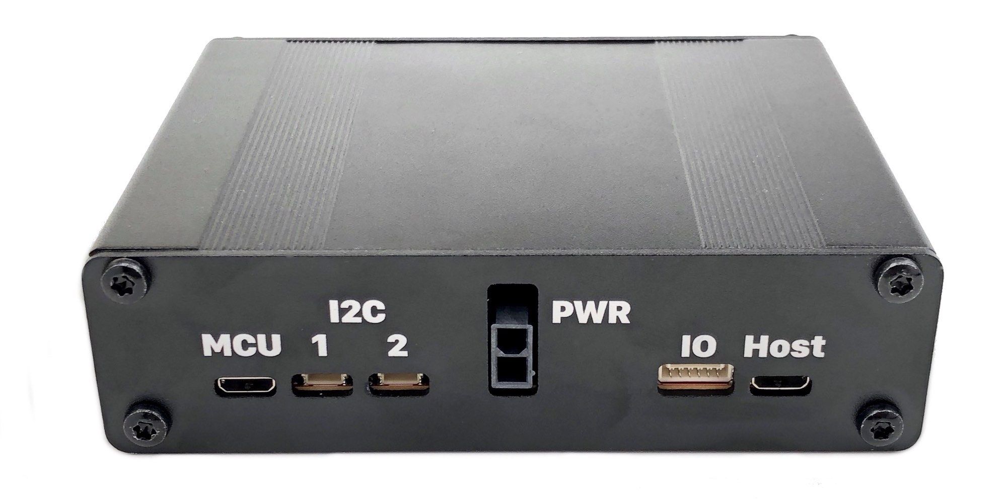
Case Production : First Articles
The first articles of the production case have arrived! They look great, and all of the thru features line up perfectly with the corresponding connections & light pipes.
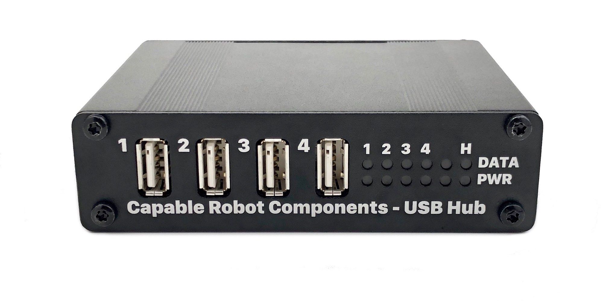
These samples were produced to validate the design of the production tooling prior to the production run itself. If there was a mistake in the design or in the fabrication of the punch tool or silk-screen, it’s much better to find out prior to making hundreds of bad parts.
Cases that you receive will have one additional change not pictured here. For CE Mark compliance purposes (and because it’s a good idea), the connector polarity, voltage range, and maximum power draw will all be printed next to the PWR connector.
The production run of cases started last week and should be arriving here in early December.
Production-Intent PCB Design
As mentioned at the start of the campaign, a final revision to the PCB design was expected prior to the production run of boards.
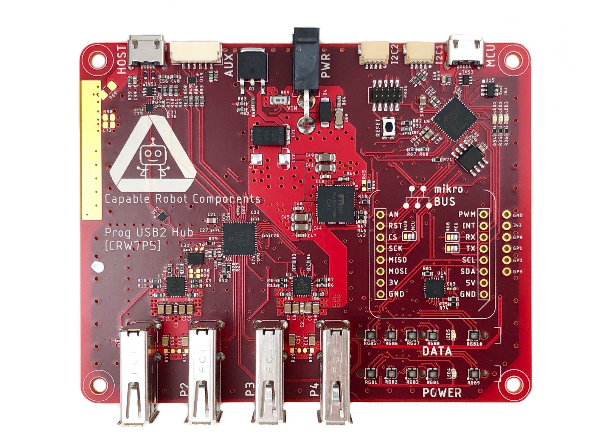
Testing of the prototypes resulted in these changes being made:
- Input power connector changed from Molex Micro-Fit to Mini-Fit
- The 5v switching regulator was moved closer to the downstream USB ports to reduce power trance length & losses.
- Many test points were added to the bottom of the PCB to support the production programming & testing fixture.
- ESD protection and EMI filtering were added to the Auxiliary IO Connector, which exposes 2x GPIO and UART of the USB Hub chip.
- A few resistor pull-ups and pull-downs were changed for better default behavior of the hardware.
- The MCU can now read fault output pin of the LT4356. This allows the MCU firmware to shut down or limit downstream USB power in the event of a power fault.
- The MCU can now switch in a 10 ohm pull-down resistor on MISO net. See the explanation below.
- The physical package of the SPI Flash chip changed to one that has more distributor stock.
- A large metal pad was added to the chassis net, to improve the electrical connection to the metal enclosure if required in EMC testing.
- Better labeling of the PCB to enhance ease of use without a case.
All of these changes have been validated, and the next step was FCC & CE laboratory testing.
A 10 Ohm Resistor on MISO net?
The USB4715 senses the loading of the MISO net during power-on to determine which ports support fast battery charging (e.g., which ports should advertise high current capability.) And unfortunately, there is no way to change this setting via the register.
A 10 ohm resistor is needed to tell the hub chip that all ports supply high currents, but a 10 ohm pull-down would prevent the SPI bus from working properly. The solution is for the MCU to switch in the resistor, bring up the USB Hub chip, and then disable the resistor, so the SPI bus works properly.
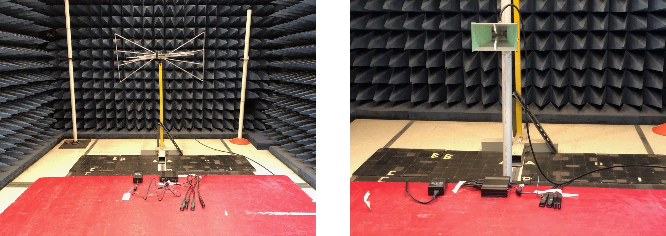
FCC & CE Compliance Testing
Over the last week the Programmable USB Hub has gone through a successful battery of tests to ensure that it does not cause interference with other equipment and that it operates as expected when subjected to interference. This specifically means the following tests:
| Group | Standard | Result |
|---|---|---|
| Conducted Emissions | FCC Part 15.107 (a)/ICES-003, Para. 6.1 , EN 55032 Table A.8 | Pass Class A limits |
| Radiated Emissions | FCC Part 15.109 (a)/ICES-003, Para. 6.2 , EN 55032 Table A.2 , EN 55032 Table A.3 | Pass Class A limits |
| Conducted Immunity | EN 61000-4-3 , 3 Vrms, 0.15 to 80 MHz on AC and Signal Lines | Pass |
| Radiated Immunity | EN 61000-4-3 , 3 V/M, 80 MHz to 5 GHz | Pass. See note below about ground loops. |
| Electrical Fast Transient Burst | EN 61000-4-4 , 0.5 kV level on USB lines , 1.0 kV level on AC lines | Pass. Recovered from faults. |
| Surges, Voltage Dips, Voltage Interruptions | EN 61000-4-5 , EN 61000-4-11 | Pass |
| Electrostatic Discharge | EN 61000-4-2 , 4 kV Contact, 8 kV Air Discharges on all ports. | Pass after firmware change. Recovered from faults. |
Below are a few sample photos taking during the EMC testing.
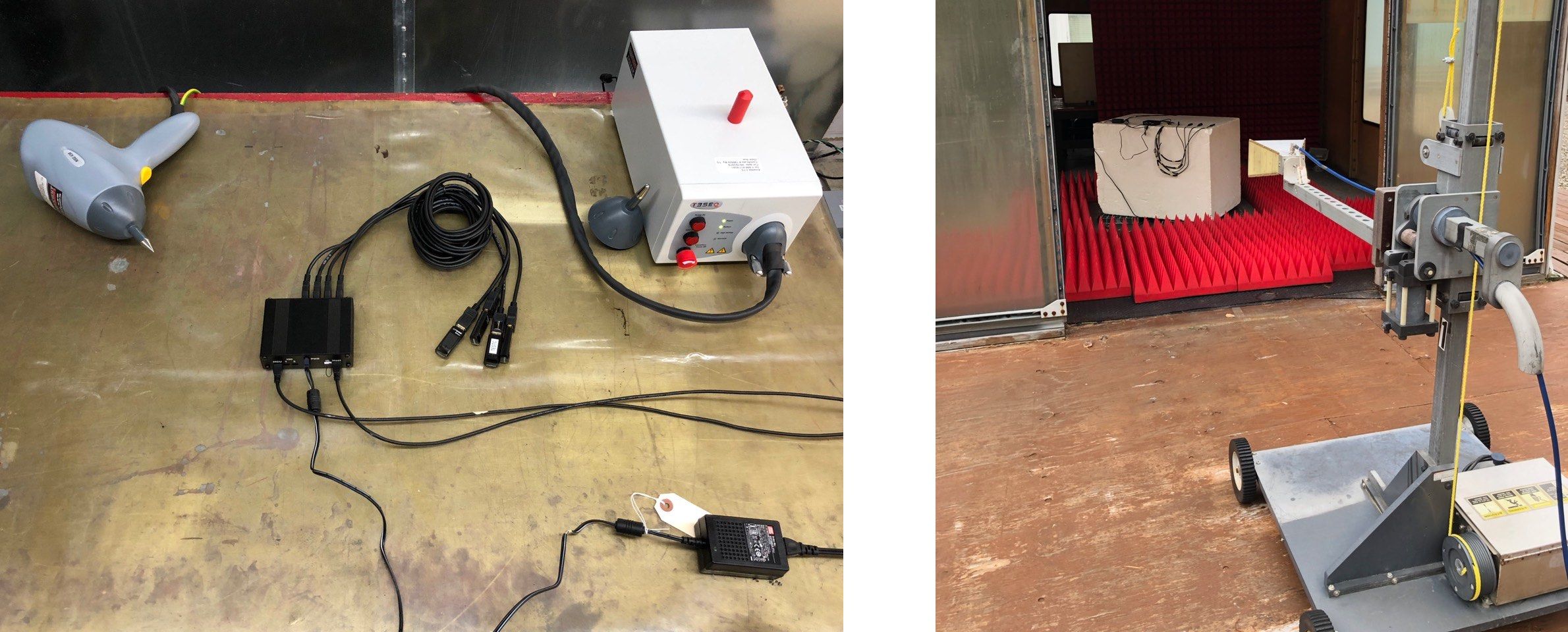
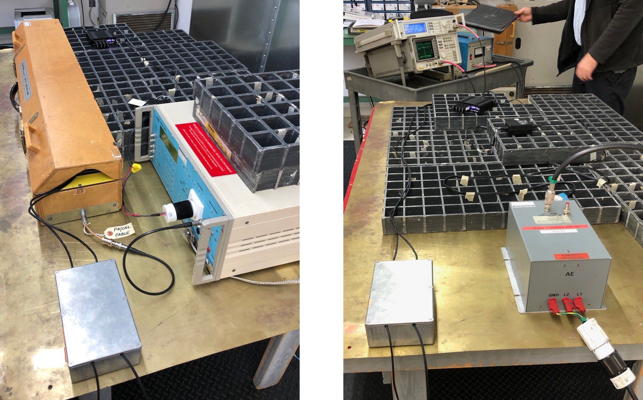
During all tests, the Hub was being exercised and monitored for faults. This included:
- Writing random data to attached USB thumb drives, reading it back, and verifying it.
- Sending and receiving random data over the serial port (via a loop-back cable).
- Reading power draw from all four downstream ports via the USB to I2C bridge.
- Reading temperature from an I2C sensor, plugged into one of the external I2C connectors.
General Notes & Recommendations on EMC Testing
There is a wealth of information online about the proper design of electronics to meet EMC requirements, and no need to repeat that here. However, I do have the following recommendations for the act of testing itself:
- Don't rely on having line-of-sight to the device-under-test (DUT) to gauge operational condition or error states. I'm glad I invested in hardware & software which exercised the Hub, reported cumulative error counts, and showed instantaneous device status. You don't want to be staring at LEDs for hours to judge system status.
- Take time during the tests to document configuration of the DUT, the support equipment, and the test apparatus -- especially if you make any changes between tests. Make sure your notes and the log files from your exercising system have timestamps so that configuration changes (if any) can be correlated to tests and results.
- Bring spares (device-under-test, interconnect cables, support equipment)! If something breaks, it's far better to have a replacement article on-site than to have to abandon testing for the day and reschedule.
- Discuss your planned support equipment with the EMC lab engineers ahead of time. I neglected to do this, and alternative support equipment choices could have saved hours of troubleshooting and testing.
Radiated Immunity & Ground Loops
During all of the tests, both the upstream USB port and the MCU USB port were connected over 2 meter cables to systems that were exercising the Hub (described above).
During the Radiated Immunity Testing (where the device under test is subjected to strong RF fields), one of the two exercising systems sometimes experienced a fault in the USB link when both the host and MCU USB cables were connected — the other exercising system had zero issues with both USB cables attached. When only the upstream USB port was connected (and the MCU port disconnected), no faults were ever observed on either exercising system.
In a discussion with the EMC Lab’s engineers, I learned they’ve seen similar issues with that particular embedded computing system in the past and do not recommend using that system as support equipment during compliance testing. It is known to be both RF-susceptible and RF-noisy when cables are attached.
During this test, the area between the two upstream USB cables created a large ground loop between the Hub and this exercising system. This loop acted as an antenna and picked up the RF energy being emitted during the test — enough RF energy to occasionally disrupt the USB data signals of one of the exercising systems.
Electrostatic Discharge Faults
The Hub was not damaged during any of the ESD testing, but the EN specification says that the product must self-recover from any faults observed during ESD testing. This means that user intervention (e.g., restart software, reboot hardware) is not allowed.
Two different lock-up conditions were occasionally observed:
- The USB Hub chip would lose the upstream connection (e.g. think the cable was disconnected when it wasn't).
- The MCU would halt (e.g. stop updating the front LEDs based on power draw).
The first lock-up was solved by a small change to the MCU CircuitPython firmware. When the upstream port connection is lost for more than a few seconds, the MCU resets and reconfigures the Hub IC.
The second lock-up didn’t impact data functionality but meant the MCU was sometimes locked-up and, therefore unable to reset the Hub IC if it locked-up. This was solved by enabling and configuring the watchdog functionality of the SAMD51 MCU. If the CircuitPython code stops executing, then it stops feeding the watchdog, which results in the watchdog resetting the MCU.
Enabling and configuring the watchdog required some additional functionality in the C-based CircuitPython runtime. In the coming days, this patch will be sent upstream to Adafruit for integration into the mainline CircuitPython release.
Thanks!
Thanks to each and every one of you who has helped us get here! Without your support, the Programmable USB Hub would not have become a reality, and we are so grateful!