Project update 7 of 10
Start of Production
With the campaign successful (woohoo!) and concluded, our efforts have now transitioned to preparing-for and starting production.
Overall, this consists of:
- Production of Custom Front & Rear Panels / Enclosure:
- Deposit with supplier (done)
- Fabrication of tooling & first article inspection (started)
- Production & Shipping
- Production of PCBA:
- Short run of final design (in-progress)
- Final verification & compliance testing
- Sourcing, Fabrication, Assembly, Shipping
- Fabrication of production test & flashing fixture
- Building of cables
- Flashing, testing, and kitting of Hub & Kits
- Finish documentation
We’ll keep you all informed as we progress thru the above, but in this update I wanted to tell you about how the mechanical design of the Front and Rear Enclosure Panels was done … with Python.
CadQuery
For the past year or so I’ve been experimenting with a Python-based mechanical design framework called CadQuery and an associated library for the creation of assemblies called cqparts.
I know this sounds a bit strange, but there are some really nice aspects of code-based mechanical-design, like:
- Easy revision control and diffs between different revision control as source files are just plain-text code.
- Physical unit understanding (via the Pint package).
- Comments! I've never found a good way to embed design intent or contextual information in a GUI-based CAD package.
- Trivial scripting of import, export, and release processes.
- Parametric and configurable parts are easy to set up and generate. Design-tables and configuration-based variant in traditional CAD tools are particularly brittle and difficult to maintain over time.
Other code-based frameworks exist, like OpenSCAD and ImplicitCAD, but I’ve been using CadQuery because:
- It's Python, not a new domain-specific language (DSL) I'd have to learn.
- It has a great geometry selection, sort of like CSS, called CadQuery String Selectors.
- It is built on top of OpenCascade, a powerful solid modeling kernel.
- cqparts has powerful mating and constraint features, including mates which modify the geometry of the underlying part.
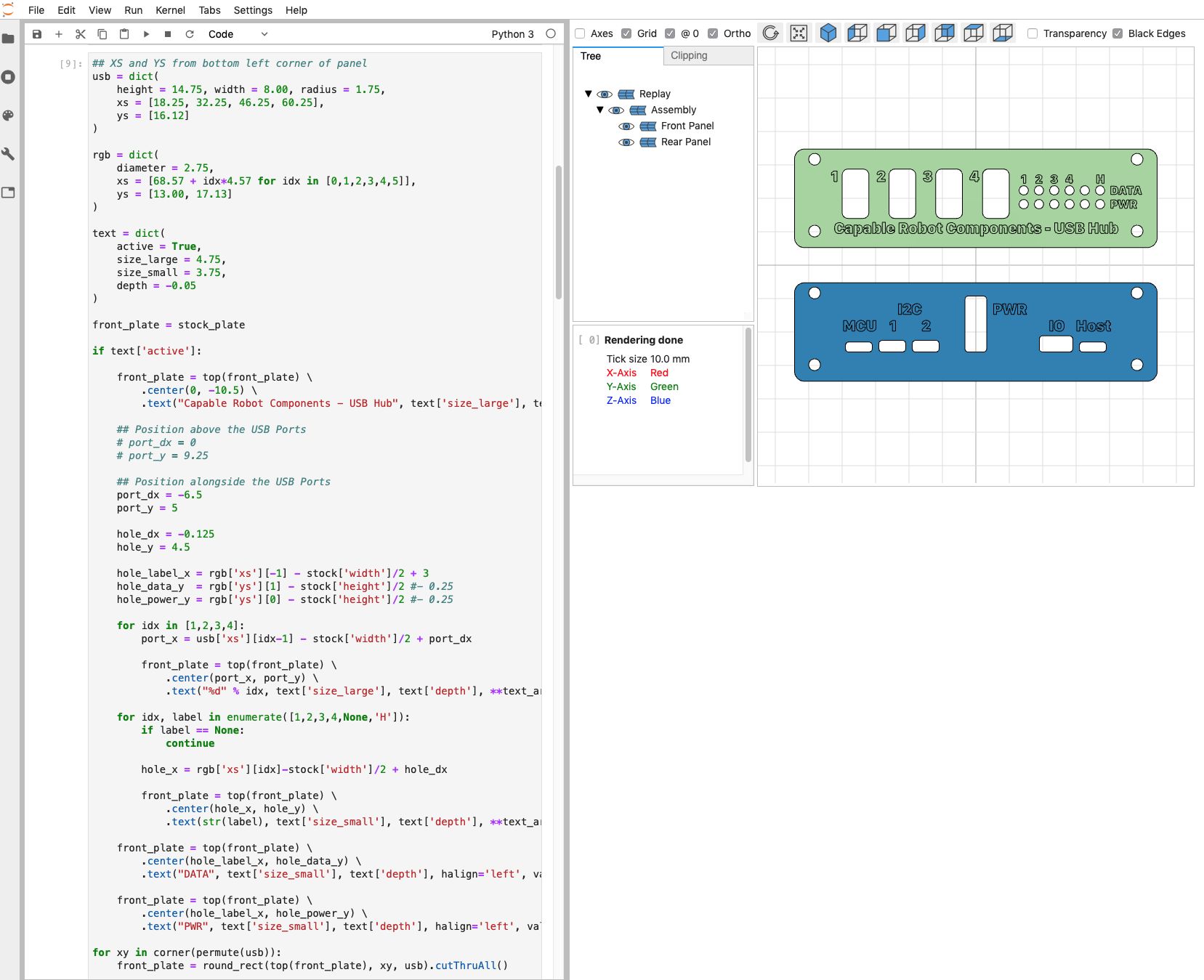
So, let’s take a closer look at how CadQuery was used to design the Front and Rear Panels of the Programmable USB Hub.
Front and Rear Panels
Below is the actual code used to generate the custom Front Panel for the USB Hub. Note, this code example does not include the text-engraving operation — it is just the THRU cutouts.
import cadquery as cq
from jupyter_cadquery.cadquery import show
from jupyter_cadquery import set_sidecar
set_sidecar("CadQuery")
# Build list of (x,y) points from xs and ys
def permute(data):
out = []
for x in data['xs']:
for y in data['ys']:
out.append((x,y))
return out
# Center Option is specified so that origin of work plane is consistent.
# The default method is to use center of mass to center the origin,
# which causes geometry to walk around if operations are re-ordered.
def top(obj):
return obj.faces(">Z").workplane(centerOption='ProjectedOrigin', origin=cq.Vector(0,0,1))
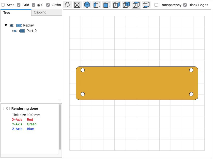
# Definition of a stock end plate with
# corner radius and mounting holes.
stock = dict(
height = 29.5, width = 108.5,
thickness = 2, radius = 3,
holes = dict(
diameter = 3.5,
xs = [-96.5/2, 96.5/2],
ys = [11.7, -9.8]
)
)
# Make the rectangle
stock_plate = cq.Workplane("XY").rect(stock['width'], stock['height']).extrude(stock['thickness'])
# Cut the mounting holes and radius the corners
stock_plate = top(stock_plate) \
.pushPoints(permute(stock['holes'])).hole(stock['holes']['diameter']) \
.edges("|Z").fillet(stock['radius'])
# Create the geometry and save to a STEP file
stock_plate.val().exportStep("stock.step")
# Show in the WebGL view
show(stock_plate, axes=False, grid=True, ortho=True, axes0=True)
And now we modify that stock plate with all of the cutouts required for the front plate.
# XS and YS are measured from bottom left corner of panel
usb = dict(
    height = 14.75, width = 8.00, radius = 1.75,
    xs = [18.25, 32.25, 46.25, 60.25],
    ys = [16.12]
)

rgb = dict(
    diameter = 2.75,
    xs = [68.57 + idx*4.57 for idx in [0,1,2,3,4,5]],
    ys = [13.00, 17.13]
)


# Transform positions measured from bottom-left corner to offsets from center (left-right & up-down) of plate
def corner(points):
    return [(x-stock['width']/2,y-stock['height']/2) for x,y in points]

# This operation could be done with rectangular cut + selection
# of vertical edges & radius operation.  But, limiting selection
# to just the newly created edges is difficult in some designs.
def round_rect(plane, center, opts):

    w = opts['width']/2
    h = opts['height']/2
    r = opts['radius']

    # Move to bottom left corner, top of that arc
    # Left edge and top left arc
    # Top edge and top right arc
    # Right edge and bottom right arc
    # Bottom edge and bottom left arc

    return plane.center(*center) \
        .moveTo(-w, -h+r) \
        .vLineTo( h-r).radiusArc((-w+r,   h), r) \
        .hLineTo( w-r).radiusArc((   w, h-r), r) \
        .vLineTo(-h+r).radiusArc(( w-r,  -h), r) \
        .hLineTo(-w+r).radiusArc((  -w,-h+r), r) \
        .close()


# Start with the stock plate geometry
front_plate = stock_plate

# Cut holes for USB connectors
for xy in corner(permute(usb)):
    front_plate = round_rect(top(front_plate), xy, usb).cutThruAll()

# Cut holes for RGB status LEDs
front_plate = top(front_plate).pushPoints(corner(permute(rgb))).hole(rgb['diameter'])

# Save STEP file
front_plate.val().exportStep("front-plate.step")
I’ve found the combination of cadquery, cqparts, and jupyter-cadquery (which allows display of geometry in the same browser window as your Jupyter Notebook) to be a powerful combination and design tool.
I hope you consider trying these open-source tools out the next time you have a part to design.
- https://github.com/CadQuery/cadquery
- https://github.com/cqparts/cqparts
- https://github.com/bernhard-42/jupyter-cadquery
Thanks!
Thanks to each and every one of you who has helped us get here! Without your support, the Programmable USB Hub would not have become a reality, and we are so grateful!