Project update 3 of 10
A Look at the Development Process
by MartijnIn this campaign update, we’ll take a look at where the idea for the Diptyx E-reader came from and how it developed over time.
The Start of the Journey
Earlier this year, I was greeted with a broken screen on my trusty Kobo Touch (from 2011). After years of being shoved in my backpack, squashed between my laptop, books, and water bottle, it had finally decided to give up the ghost. I have been getting more and more invested in open source hardware and software recently, as I prefer to have full control over the things that I own, e.g., I don’t want to use a device/program where features can be removed or altered through a forced software update. Looking for an open-source ereader, I found several promising projects, but none of them had all the features I desired. That’s when I decided to make my own.
First Proof of Concept
The first working proof of concept was made using an ESP32-S3 Dev module, a 5.83-inch black/white/red E-ink display, and some very poorly soldered electronics. With this test setup, I was able to read an EPUB from an SD card, and display text on the screen in Unifont. The code for extracting metadata from EPUB files on an ESP32, and the idea of using tinyXML2 for parsing the HTML-like files, was adopted from Atomic14’s DIY ESP32 EPUB reader. The other code, such as for rendering the EPUB files, drawing Unifont, and driving the displays, was custom.
With the principal concepts proven, I moved on to making it into a self-contained, portable device.
First Prototypes
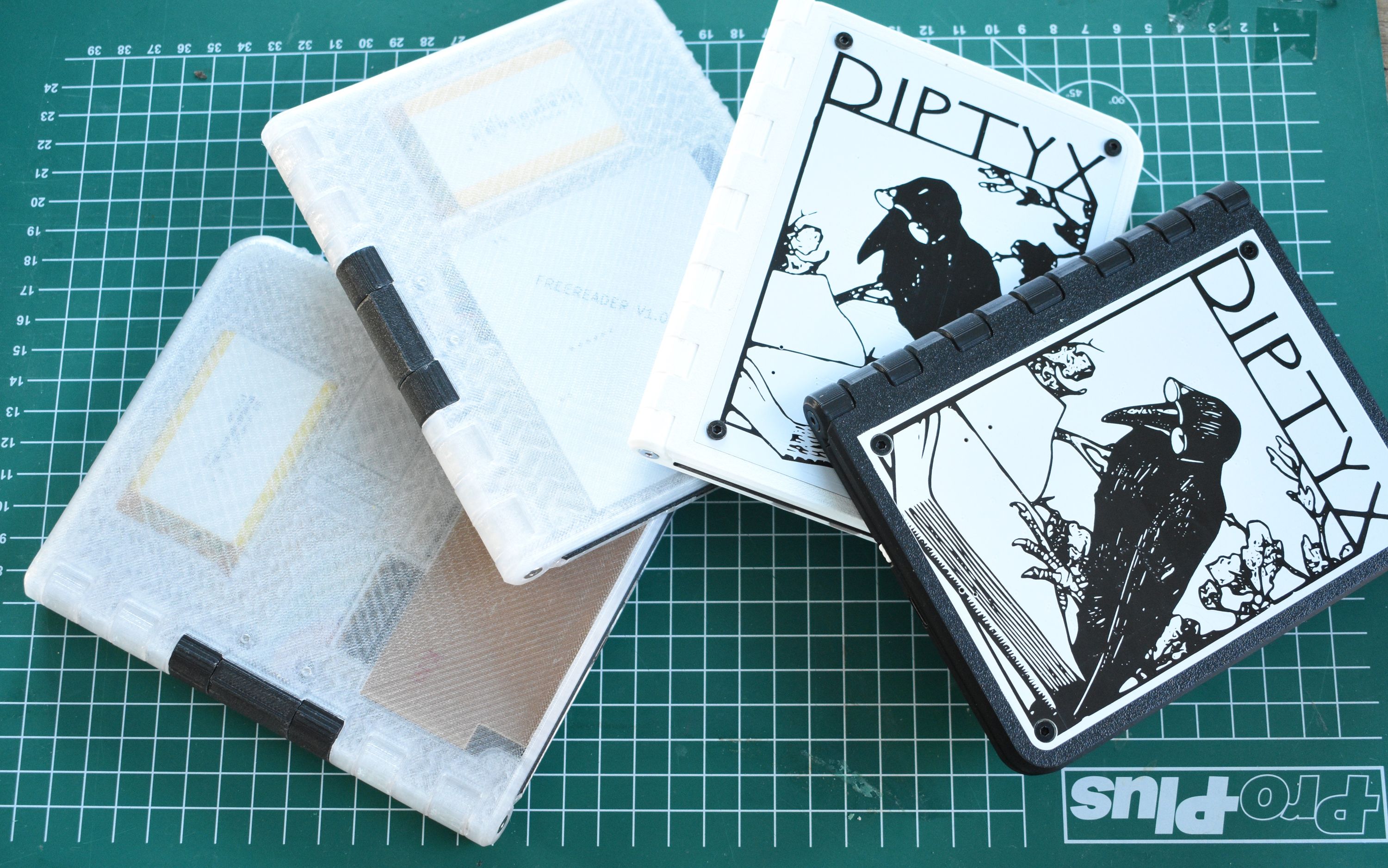
Using many off-the-shelf components and modules, a DIY-etched PCB, and many wires, the first full prototype was constructed. The decision to use a clamshell design with two screens was mainly to ensure the screens are protected without requiring some sort of protective case. The prototype worked quite well, but had some major flaws: Firstly, the transparent plastic case looks interesting, but allows sunlight to reach the back of the displays. Direct sunlight can activate the TFT transistors on the display, resulting in visual artifacts. Secondly, books could only be transferred by opening up the device and taking out the SD card. And lastly, the large plastic case pieces were always slightly warped, so they wouldn’t fit well around the glass displays that don’t tolerate any bending.
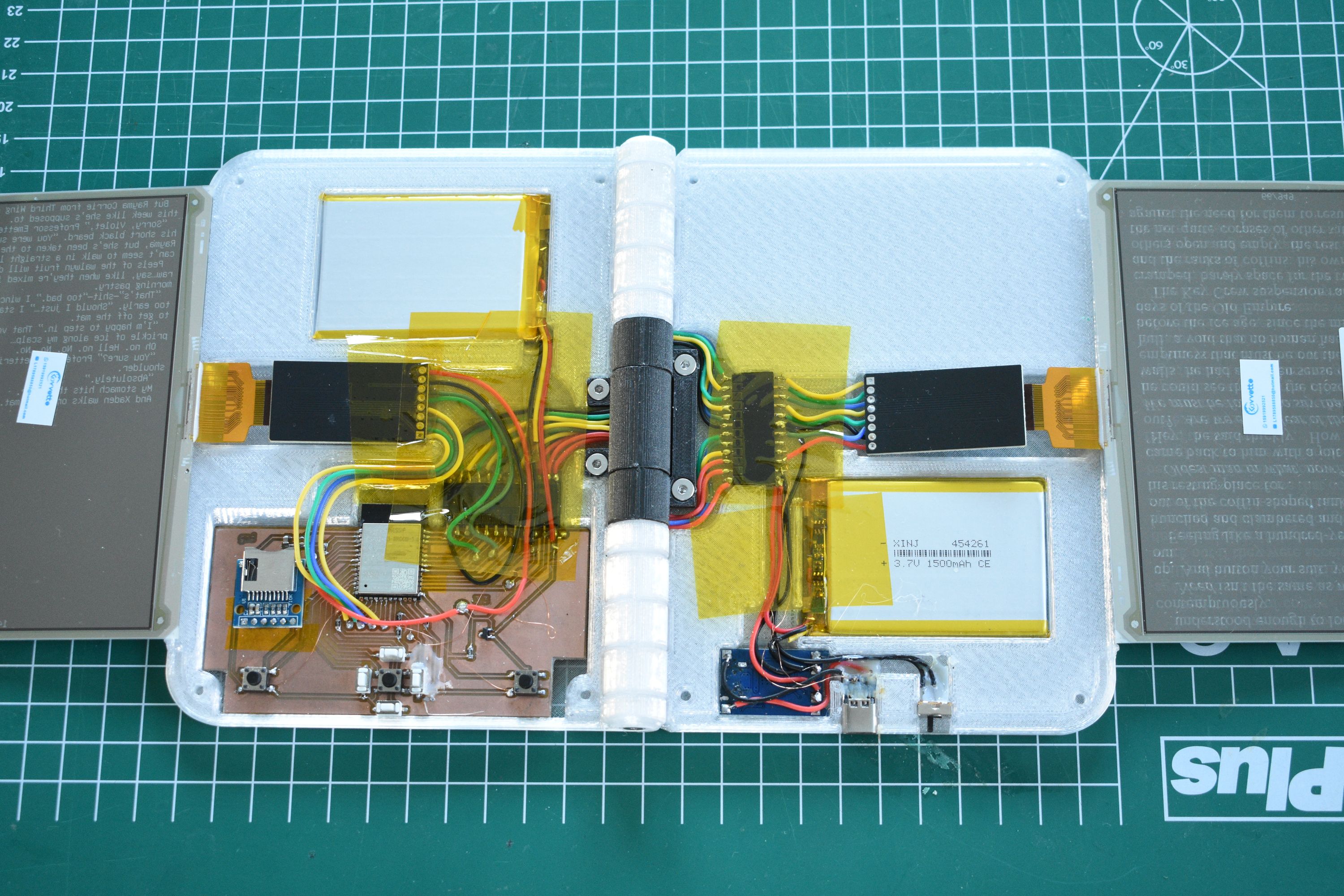
The next prototype was very similar in design, but was constructed with professionally made PCBs. These PCBs contained all the electronics that were previously spread out over several modules, such as the charging circuit, display drivers, USB port, etc. It still had many of the flaws of the initial prototype though, and was quite bulky as well.
A New Design
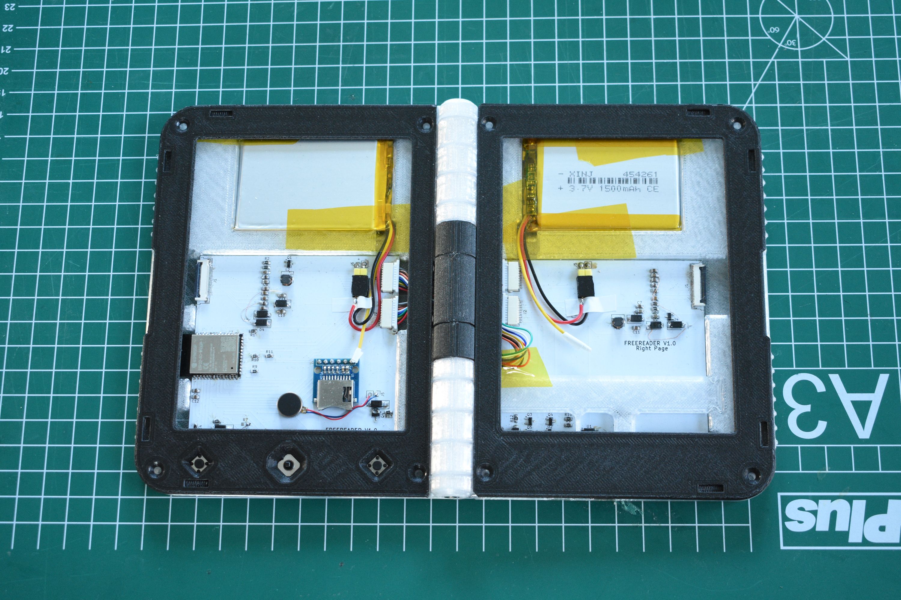
The next iteration was a leap forward. In a quest to make the design as compact as possible, the PCBs were moved to the outside of the device. These thick circuit boards, made out of fiberglass composite, made the design significantly more rigid and made it possible to add artwork to cover the device. Also, by positioning the displays more efficiently, the design could be a lot more compact.
With this version, the bulk of the software development was completed, such as the support for images, CSS stylesheets, custom fonts, a proper menu, and much, much more.
Many, Many Iterations
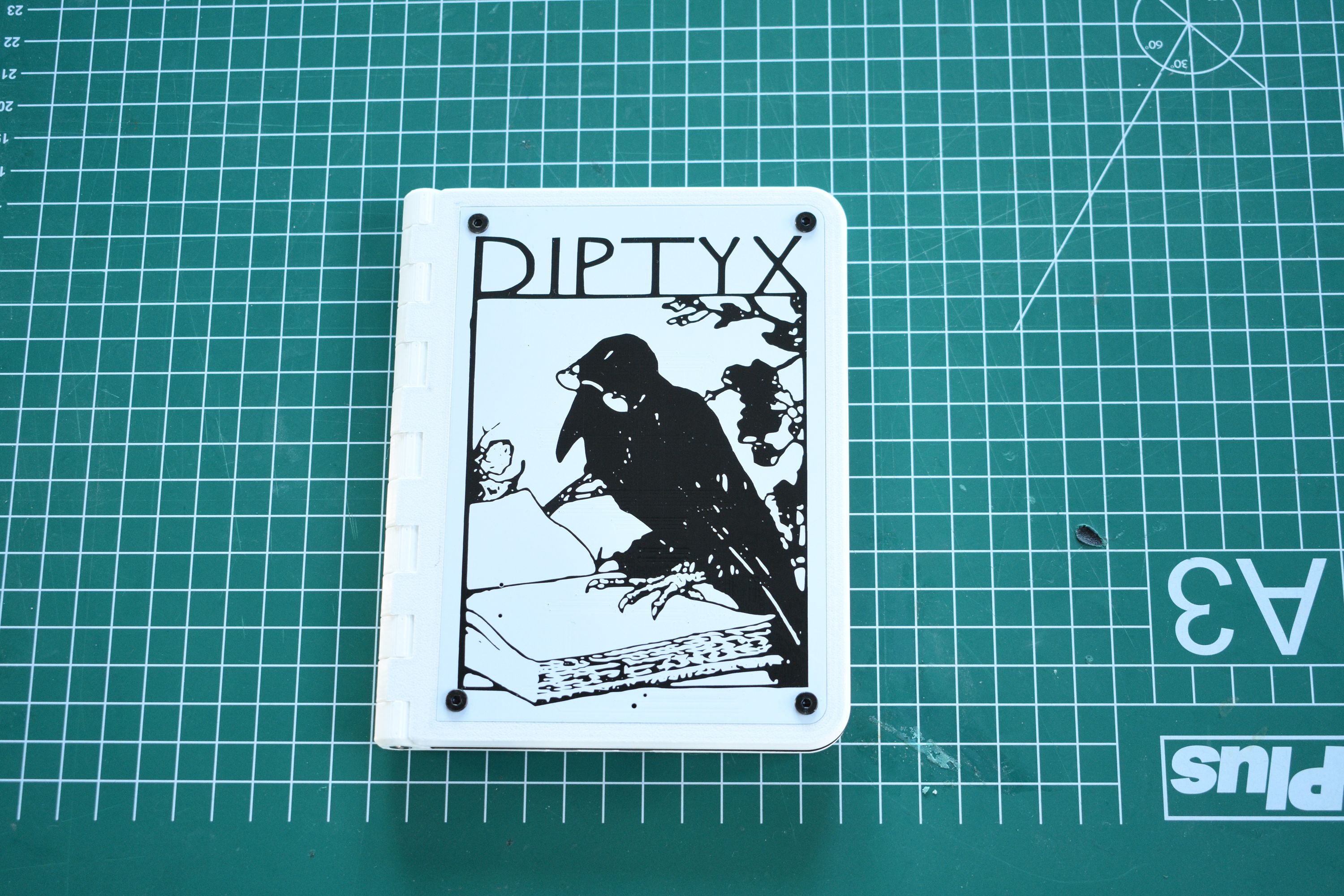
This design went through many further iterations, but stayed roughly the same. The artwork was re-made with higher quality, the electronics got more power efficient, all buttons and LEDs got white plastic covers, the PCBs went from two layers to four layers, so no circuits are exposed on the outside, and the five-way button was changed into a three-way button. The part that was most iterated on, however, was the outer casing. Through the course of dozens of test-prints it saw many small changes. From tuning the tolerances to adding snap-fit clips to including small geometries that nudge the slicer into the right direction.
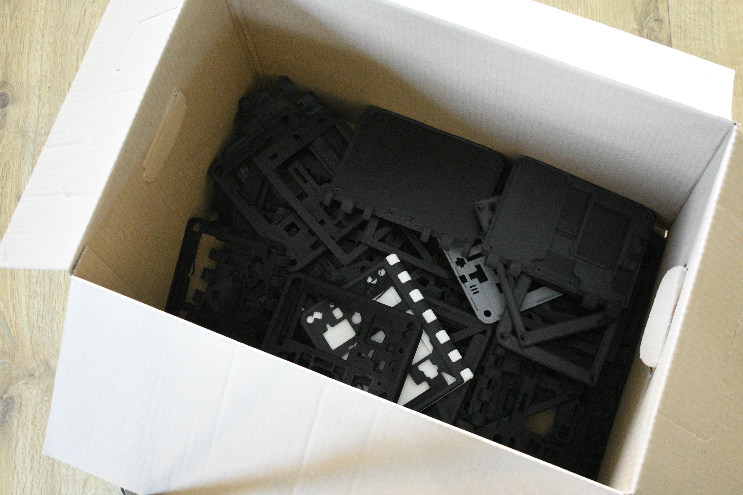
Now, apart from some small details here and there, the design is in a good state and we are very happy with it. In a later post, we will go over it in detail and explain which part does what and why it was designed in that way, stay tuned!