Project update 14 of 14
Dev Edition Production Begins
by Aleksa BHello everyone!
Once again I’ve managed to get my head above water long enough to sit down, cozy up inside during this snowstorm, and write you all an update. I’m going to try to remember all the stuff I’ve been up to over these months and start right after the last update.
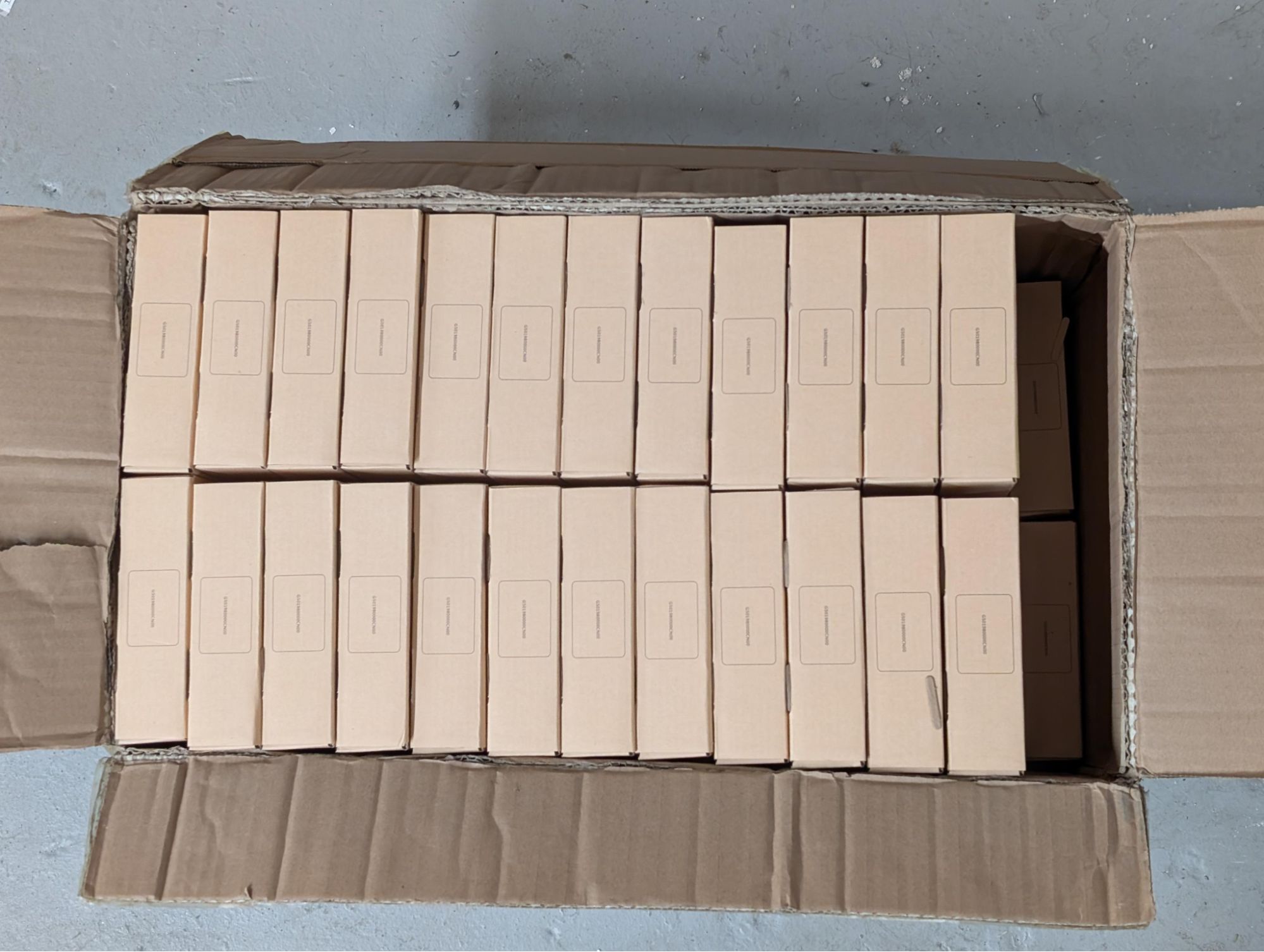
Adeptly Acquiring Adaptors
With this box filled with boxes filled with PCBAs, we have enough thunderbolt adaptors to build all the TS-USB4 units.
C-N-C, it’s dyna-mite
With apologies to Angus Young and co… Milling the brackets turned out really well, even though they were made of steel and it was my first time milling anything!
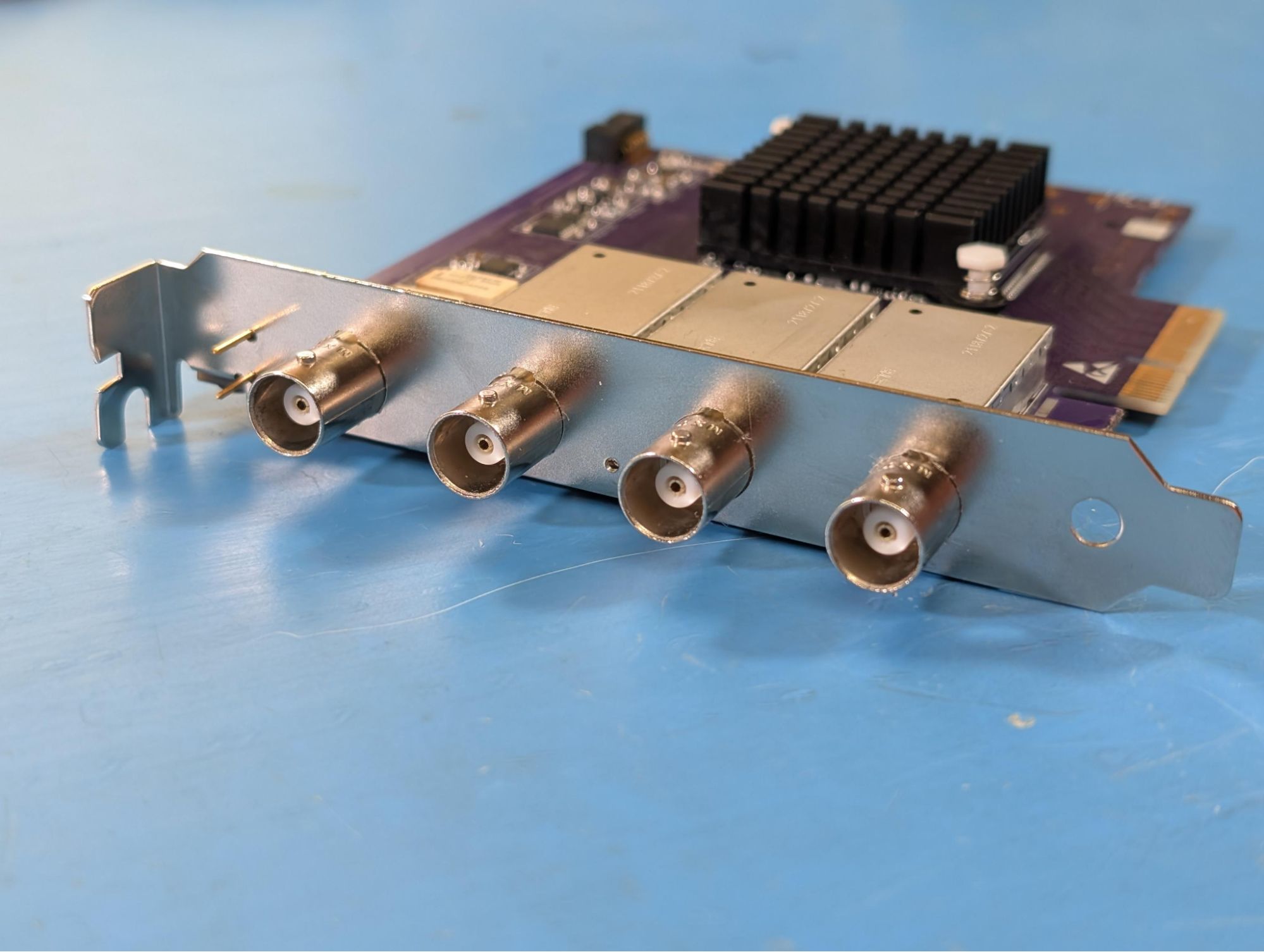
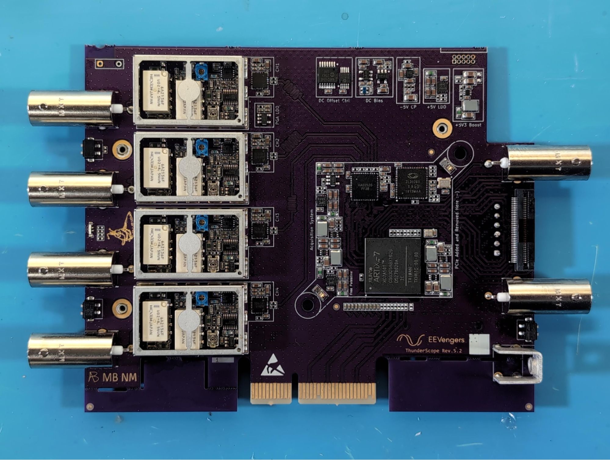
Rev 5.2 Hand Build
The Rev 5.2 boards came in and I had to build one up in a hurry. Thankfully everything worked just fine despite tempting fate and only building one unit that could be used for CE certification testing.
Staring Down the Barrel of an Antenna
There’s nothing more stressful in my experience as a hardware designer than setting up your product in an RF test chamber and waiting to see if some mislaid trace or wayward via betrays you. I wasn’t soaking in cortisol alone though, as I was sharing some chamber time with Micheal Ossmann of Great Scott Gadgets, who was going through the same exact test procedure (since we’re both making test equipment) for GSG’s HackRF Pro. A huge thanks to him and to GSG for letting me tag along with my (assembled the day before) Rev 5.2!
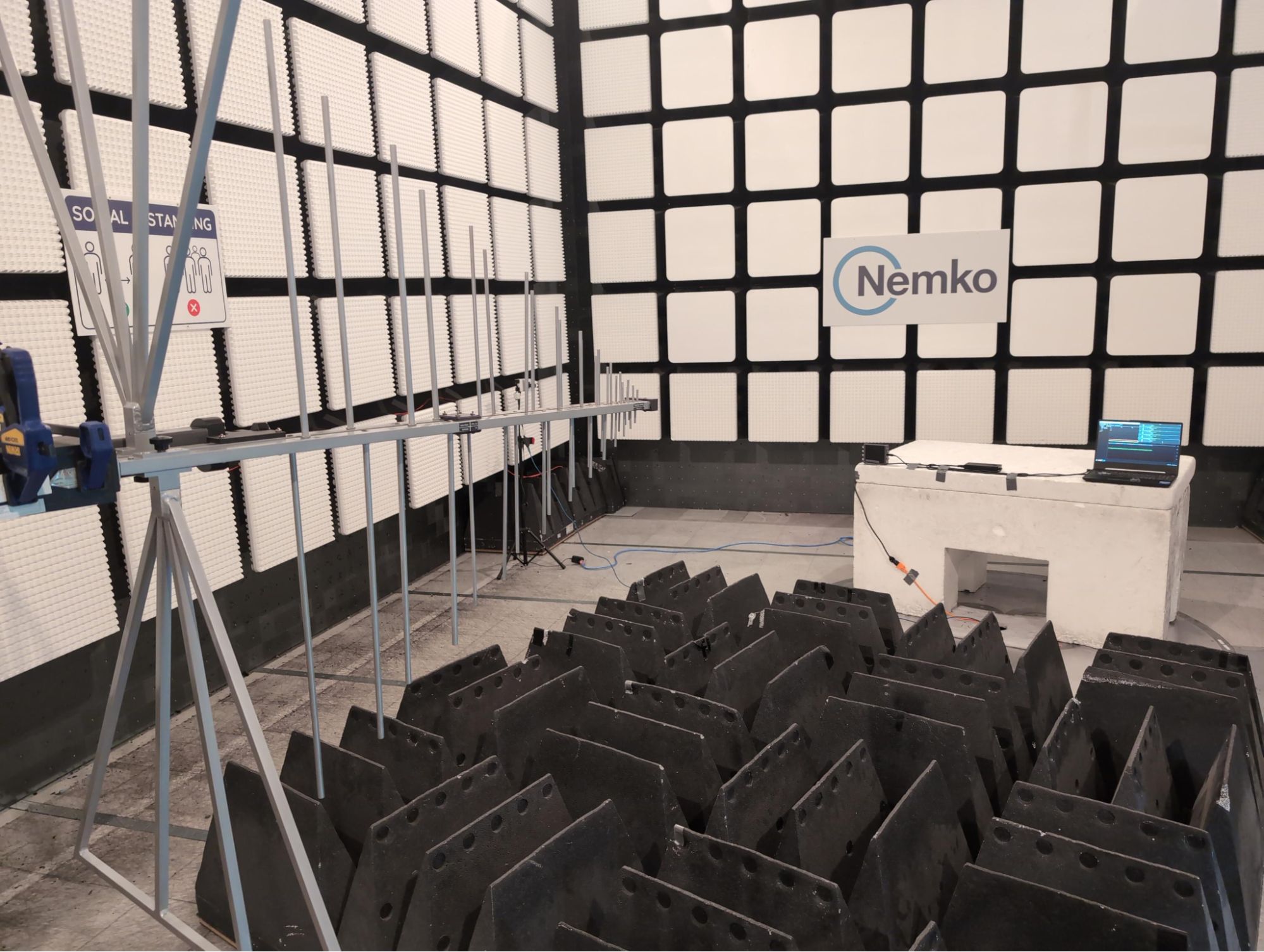
In a shockingly positive turn of events, we stayed under the limit for radiated emissions, did not stop functioning under interference, and avoided any damage from ESD. With this, I had enough information to comfortably self-certify the design for CE. Another hurdle cleared on our way to production!
Macs-imum Performance
We have everything working end-to-end on MacOS and the performance you can get out of a little M4 MacBook Air is really impressive:
I’m really proud of all the work that’s gone into making TS work on every major OS, which leads me to some more good news…
One Step Closer to a Plug and Play ThunderScope
After much back and forth with support (and yes, there was a mandatory chatbot involved), we finally got registered for Microsoft’s Windows Hardware Developer Program. Once we get our driver past the barrage of automated tests (and potential manual vetting), TS will be completely plug and play on every Windows 10 & 11 machine, as the driver will be distributed and installed via Windows Update.
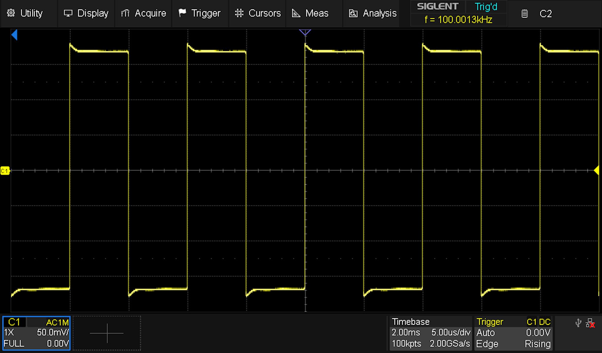
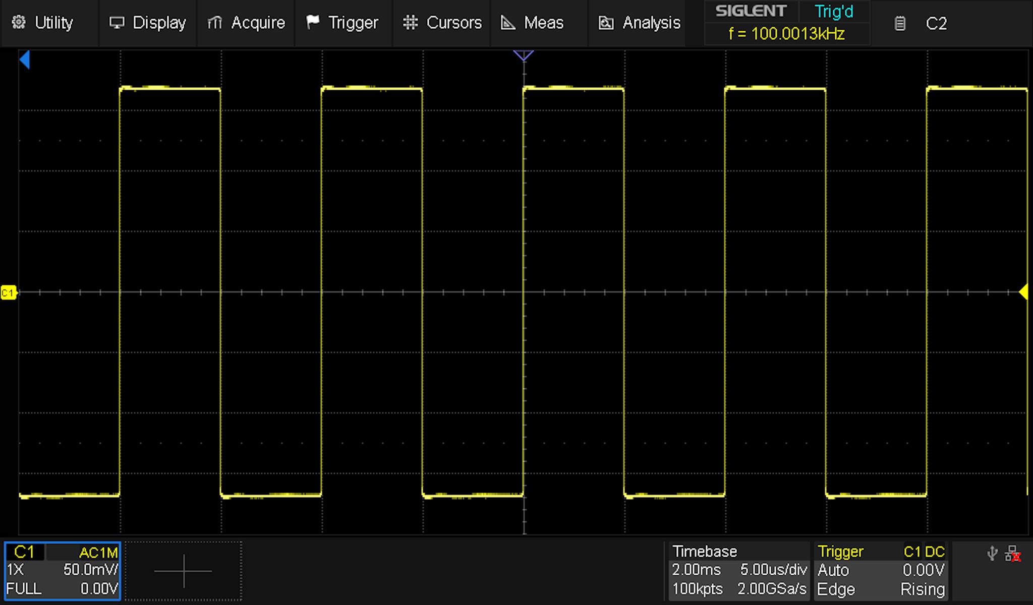
The Return of the Un-Square Wave
After testing the 400kHz correction circuit, I saw these very slightly wobbly square waves and almost lost it. I tried just about everything and nothing reliably got me the last few dozen mdB towards perfect flatness.
In the end, the issue had a fix, but it wasn’t applied to the board, it was applied to the designer. I looked closer at the specs of other scopes and found this was about par for the course and with great difficulty I ripped myself away from this (but not after some minor tweaks that did make it into Rev 5.3).
Ghost in the Shield
I had an issue where the attenuator compensation would change once I installed the lid onto the shield can (pictured below is the difference between lid off and lid on) and got worried that we wouldn’t be able to adjust the trimcaps with the lid off during assembly.
The solution I came up with was to put holes in the lids to allow adjustment without disturbing the circuit.
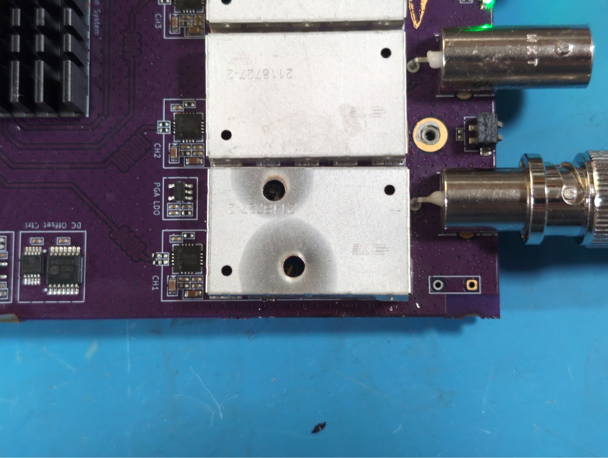
I tried this on another channel and didn’t notice much of a difference. I wondered why and searched for what could be causing this change of behaviour. I figured out that the metal tab that’s there for pick and place machines was removed on Channel 1 (to make room for reworking the components under the shield) and wasn’t removed on the other channels!
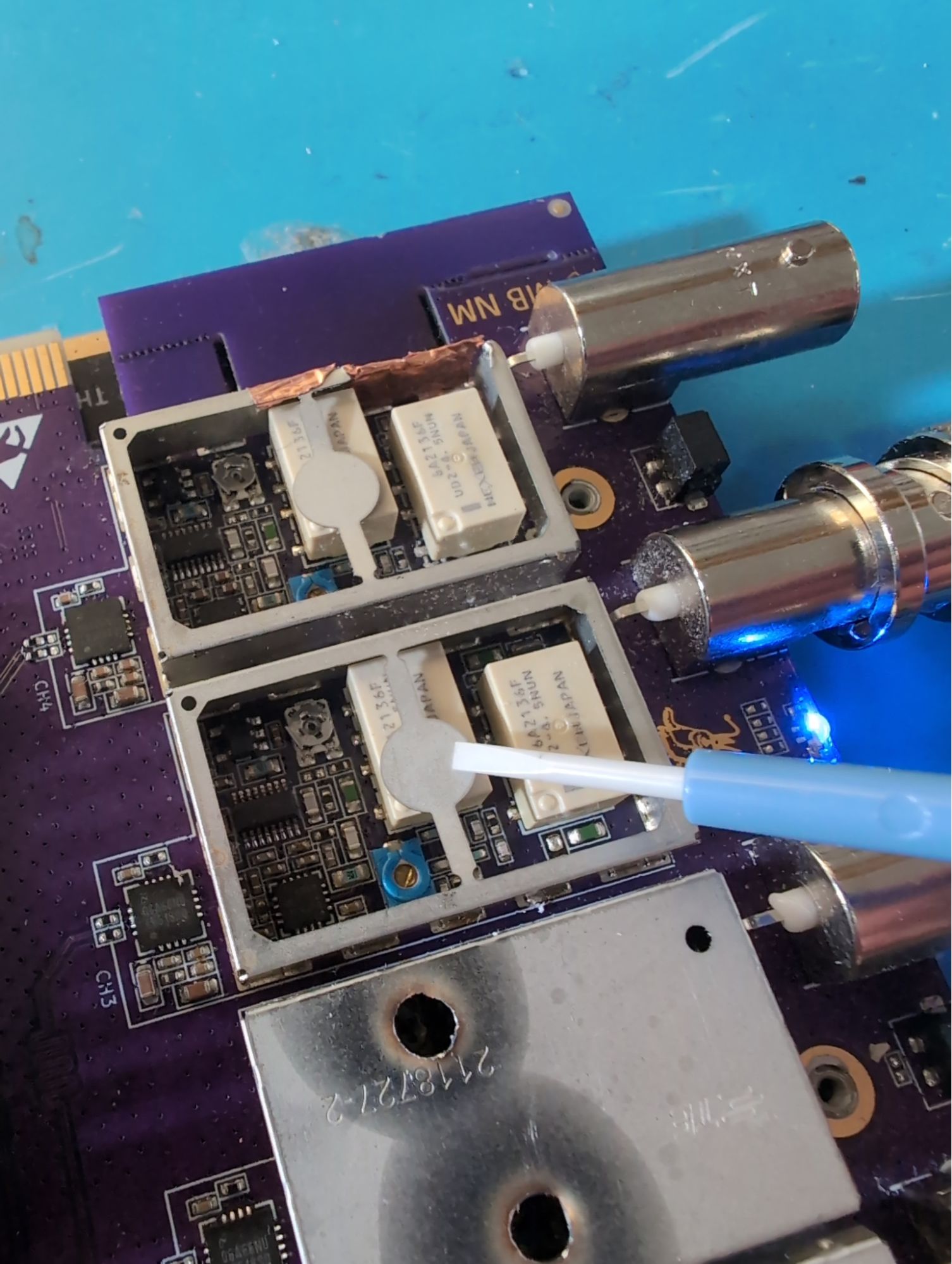
This tab goes right over the attenuator relay, which adds a tiny bit of capacitance in just the right location to cause almost exactly the same change as the lid being on a shield without the tab. So this wasn’t the issue I thought it was, and we don’t actually need to put holes through the lids - all because of the fortunate placement of the relay with respect to the shield can. The fact that this is what was happening was really good to learn, there’s nothing scarier than things working for reasons you don’t fully grasp.
“Works on My Machine”
I sent a PCIe unit out to Andrew Zonenberg, who tried it on a few hosts with no success. We thought it could have been ESD damage during shipping or something, but the plot thickened when it worked on my usual setup. Turns out, some hosts will unilaterally swap the lanes of the PCIe interface without the device having to support it. Our PCIe gateware (litePCIe) does not support lane swapping (which I knew), but I didn’t realize the lanes were swapped until the alternative vendor provided gateware worked first try.
This was also the good kind of red herring issue, as it led to discovering that we weren’t following PCIe spec to the letter - both for decoupling cap value, and for how we handled CLKREQ#. Neither was enough to actually be the cause of this issue on the systems tested, but fixes for these will be in Rev 5.3 to avoid this issue rising from the dead later on.
Clock Input Coupling
Nate was implementing the refclk controls, found that the refclk input wasn’t reported as valid, and suggested adding a coupling cap as per the datasheet. I tried it out and it worked, the fact that the designators for these zero ohm resistors started with C was a giveaway that I probably changed them at some point - d’oh! As with all these issues, I’m glad we discovered it now rather than later. Speaking of…
One Last Major Issue, As a Treat
This is a fun one. This whole time I have been testing the front end’s high frequency performance directly, through the two UFL connectors on the back of the board that I put there for this very task. The ADC’s differential input was terminated with a 100 Ohm resistor, and driven by the PGA’s series-terminated 100 Ohm differential output, should look just like the test setup I use, right? Well if that was right you wouldn’t be reading this… So what went wrong?
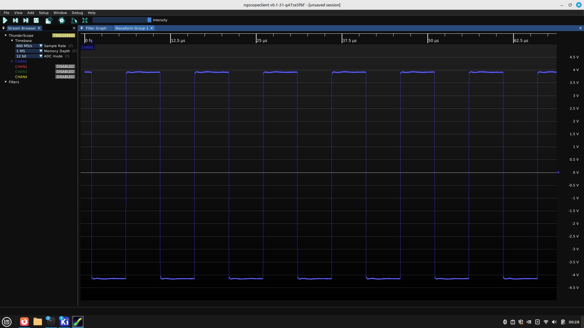
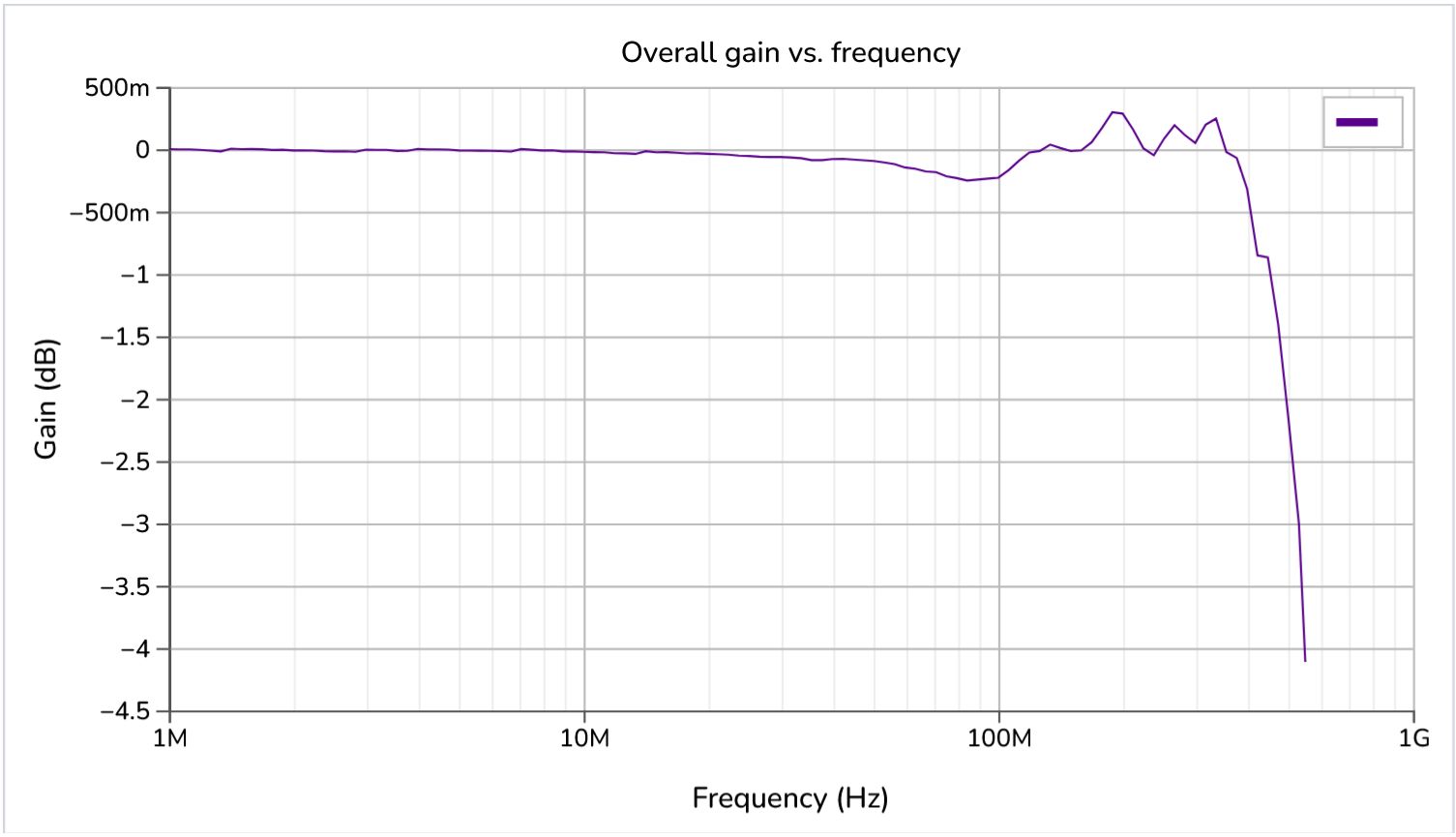
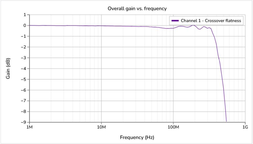
Mark upgraded his function generator and extended his end to end testing to 100 MHz, where he found something strange - the frequency response was down by -1.5 dB at that frequency (see plot of channel 1, below). That very much didn’t match my front end testing results!
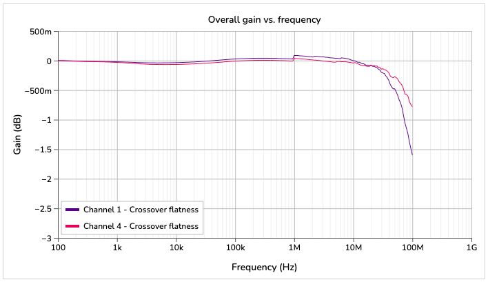
The reason for this discrepancy was the ADC itself, it had up to a whopping 11pF of input capacitance! This formed a filter with the series output termination built into the PGA, so it had no chance of reaching the kind of bandwidth I was measuring from the front end in isolation. This connection from PGA to ADC wasn’t touched since 2019, where I remember changing the input circuit for the ADC to a simple termination. I thought I remembered testing the end-to-end response up to higher frequencies, but in a project so long spanning and with so much of this span so poorly documented (pretty much everything pre-launch was on Discord somewhere, and the pre-2021 stuff was nowhere but my own head), an issue like this can sneak in. So enough excuses, what did we do about it?
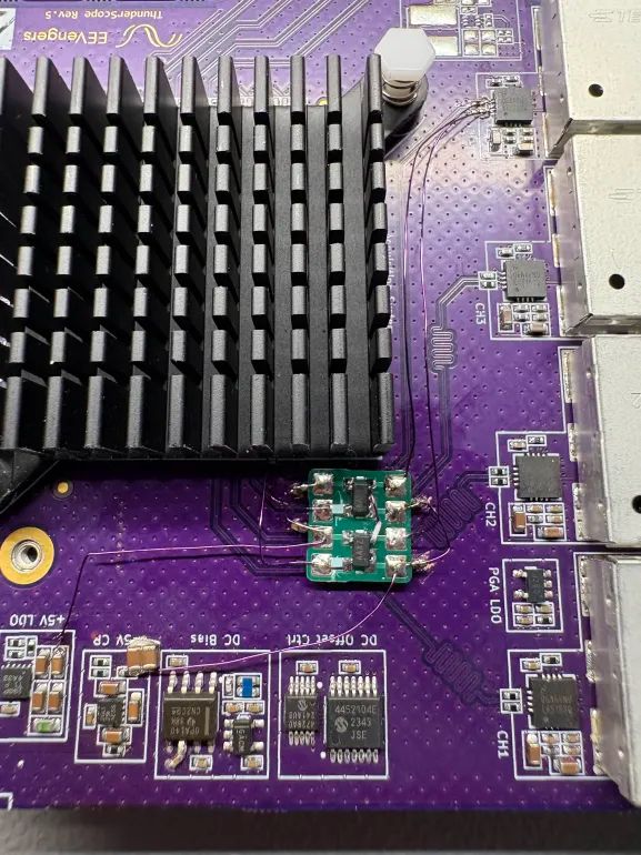
Mark took a crack at it right away, bodging in two MAX4200 open-loop buffers to drive the ADC much harder than the PGA could. This resulted in the Channel 4 results in the plot shown above.
I went ahead and replicated this on my end and tested it with the RF signal gen I mentioned in the last update (thanks again, kindly Corvid!). I found that it had about 350 MHz of bandwidth, not bad, but not to spec either.
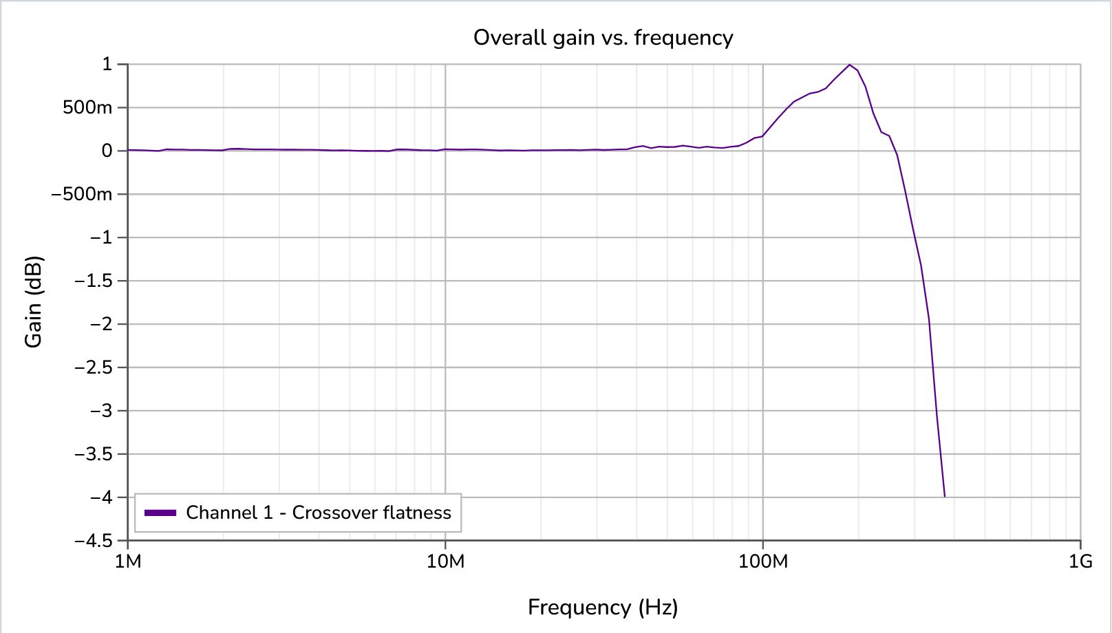
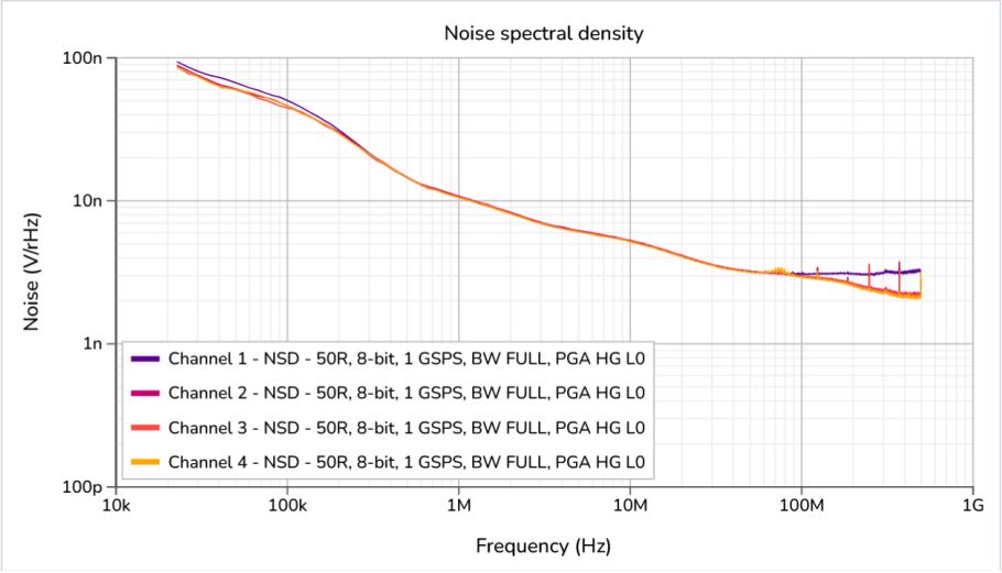
There was a downside to this added bandwidth, we had a bit more noise now (up to 75uVrms from 71uVrms). You can get a good idea why based on the change in the Noise Spectral Density (NSD) below.
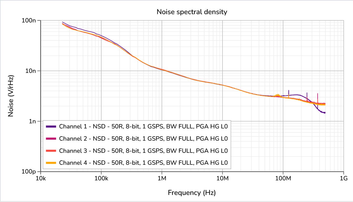
Those extra microvolts of noise live in the space between the purple Channel 1 line and the others, making this increase in noise directly the result of the extra bandwidth of the circuit. This tradeoff between noise and bandwidth means that speccing 80uVrms of noise at full bandwidth has gone from a well-padded estimate to an immense challenge!
As with most of these kinds of tradeoffs, the best thing to do is try everything and see what gets you closest to where you want to be, so I fired up the CNC mill again and ordered some promising contenders for our new ADC driver.
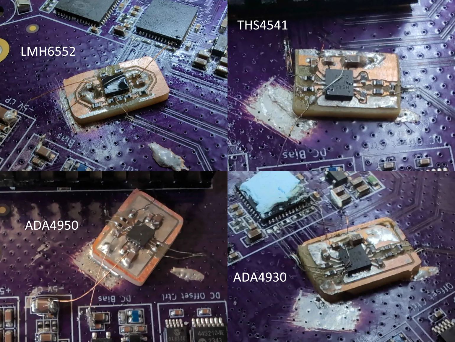
The two standout choices were the LMH6552 and the ADA4930. The LMH6552 had more bandwidth on tap and could clear 500 MHz while operating at a gain of two (which means we need to use less digital gain on the ADC).
This was a really flat response, but to my surprise the NSD showed peaking which caused the noise performance to be worse (as the area between the lines is much bigger). This resulted in a full bandwidth noise measurement of 93 uVrms.
I found that the only way to flatten the NSD and minimize the noise was to increase the gain to 2.8x. This resulted in a full bandwidth noise measurement of 83.7 uVrms, that’s pretty close to the original 80 uVrms spec, but “full” bandwidth here isn’t 500 MHz, so it’s a bit worse than it looks.
However, this dropped the bandwidth to about 430 MHz.
This was a tricky problem! We needed to keep the front end frequency response intact, so we required a lot of bandwidth and flatness from the ADC driver, which meant it would generate its own noise over a much larger frequency range. This noise gets folded back along the nyquist frequency (500 MHz) and shows up in our NSD. The increase in gain brought the signal gain closer to the noise gain (they are different in this case! noise gain = signal gain + 1) and the bandwidth down, meaning less high frequency noise content. These are the reasons why there was less noise at higher gains.
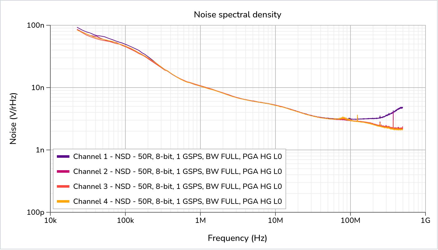
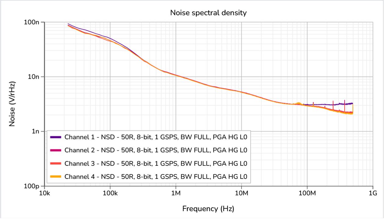
Thankfully after testing a few other parts, I came across the ADA4930. This part had a good frequency response right off the bat, reaching ~460 MHz with +/- 0.5dB flatness out to 350 MHz.
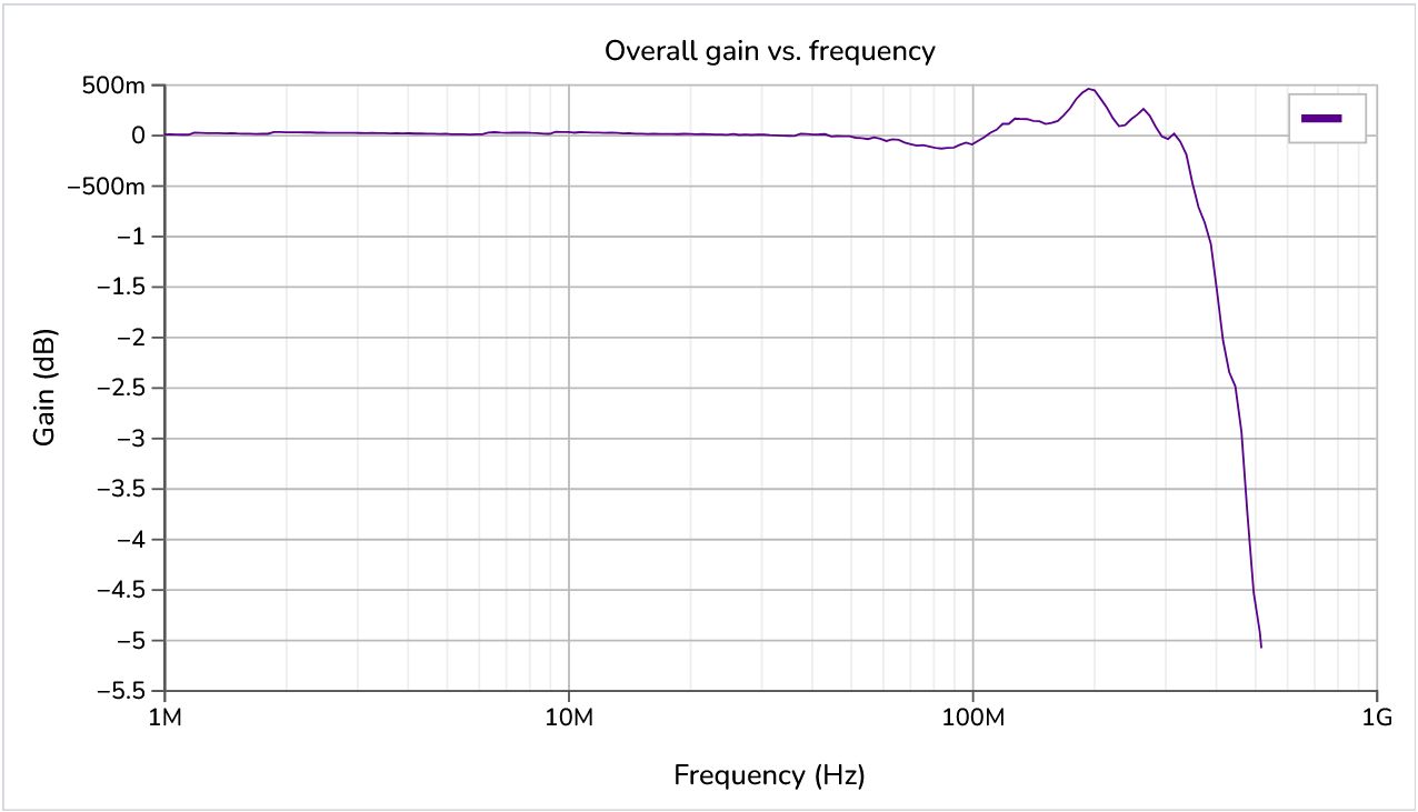
And much to my surprise, the NSD was also nice and flat. This resulted in a full bandwidth noise measurement of 83.5 uVrms, which matches the results of the LMH6552 with a similarly flat NSD.
It was still a bit off of 500 MHz, but we could probably get there with some tweaks. What matters for component selection is that this part has the highest bandwidth for a flat NSD. It also had a bunch of other advantages over the LMH6552 which I detail in the last comment of this issue.
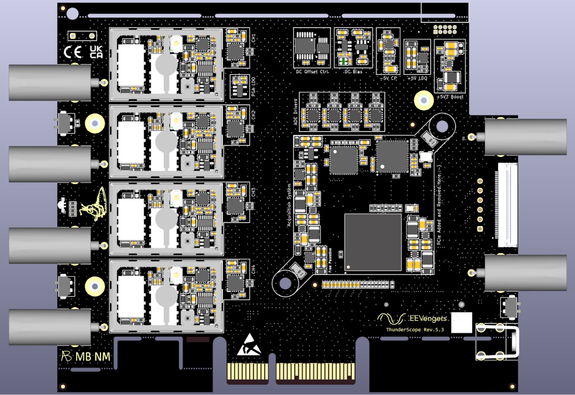
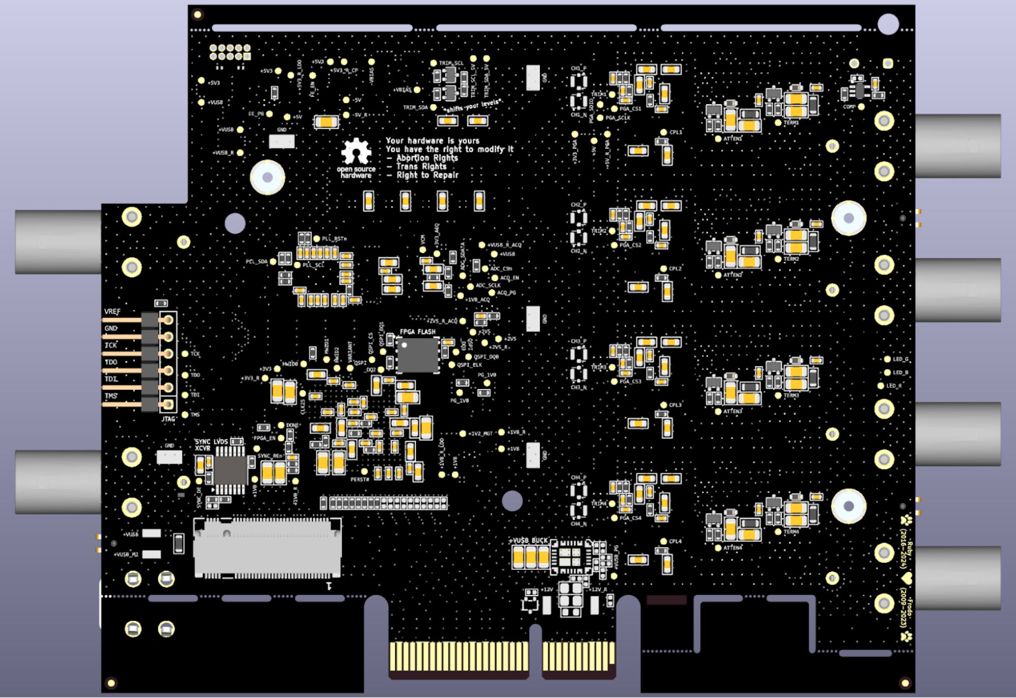
And That’s a Wrap: Designing the Last Rev of ThunderScope
With the new ADC driver chosen, it was time to design Rev 5.3. You can find a list of changes by searching the github issues for the Rev 5.3 ECO tracker tag. Below are the final renders of the TS-USB4 variant PCBA.
At the time of writing, the design has been sent off to four CMs for quotes. I will be selecting a CM at the end of January and getting all the dev edition units built, plus some extra units for our internal use. In parallel, I will be doing a hand build of this rev when I receive the bare boards on Feb 2nd. If the hand build shows some major issue I will have time to hold the design, otherwise I will not be modifying the design further. My priority right now is preparing for assembly and minimizing further delays to shipment of the dev edition units.
This focus on delivery will come with a small compromise, the bandwidth of the dev edition units will be a bit short of 500 MHz, likely falling in the 450-500 MHz range. The projected noise performance will be 86.5 uVrms based on long-term testing of the Rev 5.2 unit modified with the ADA4930. This is higher than the 80 uVrms spec and unlike the bandwidth, will not be able to be improved (it will likely get a little worse once we hit exactly 500 MHz).
The reason for this is in the signal chain. With a flat NSD, the dominant factor setting the value at which it flattens out is the input buffer, so we would need to completely redesign the front end in order to get lower noise than what we have now. This would take an immense amount of time and effort and is not something I want to do with hundreds of people waiting for the units they paid for. Therefore the most prudent decision here is to accept a slightly worsened noise spec. As mentioned above, this spec was set with an incomplete view of the complete system bandwidth, and I would like to apologize to you all for this mistake. Besides these points, ThunderScope should meet the rest of our specs and be a trusty addition to your lab benches for years to come!
The Final Countdown: An Updated Shipping Timeline
The lead time from the best quote I have so far is 4 weeks, but this does not count CNY, so the assembled boards will probably come back mid-March. I will be getting everything set up for incoming tests, box build, and calibration in the meantime. We already have the instructions written for box build and the calibration utility is ready for production, so the only remaining work is on the bed of nails fixture as well as sourcing a few more parts, like the end caps and interposers. Therefore, I expect to ship the dev edition units to Crowd Supply at the end of March. I plan to wait two weeks after the dev editions get to backers before sending out the order for the rest of the Crowd Supply units. So given there aren’t any hardware issues discovered in that time, we will order those boards Mid-April and they will get back to us by the end of May. This is a bigger batch so it’ll take a bit longer to ship out, but we’ll already have nailed down the process from the first batch, so I think sending them out at the end of June would be a reasonable estimate.
So there you have it folks, Dev Edition units by the end of March and all the rest by the end of June! It’s exciting to have such a concrete estimate for once and I’ll be sure to give you all a brief update as soon as we get the assembled boards in :)
-Aleksa