Project update 13 of 14
Ngscopeclient v0.1 Released and One Last Hardware Rev
by Aleksa B, Andrew ZAleksa here, I have lots of weird and wonderful tales of circuit design to share, but first there’s some exciting news from Andrew Zonenberg on the software front:
Hi everyone - Andrew from the ngscopeclient project back again with a development update.
There ended up being a lot more work to do than we expected (isn’t there always?), so it took longer than planned, but we finally shipped the v0.1 release of ngscopeclient on the 11th.
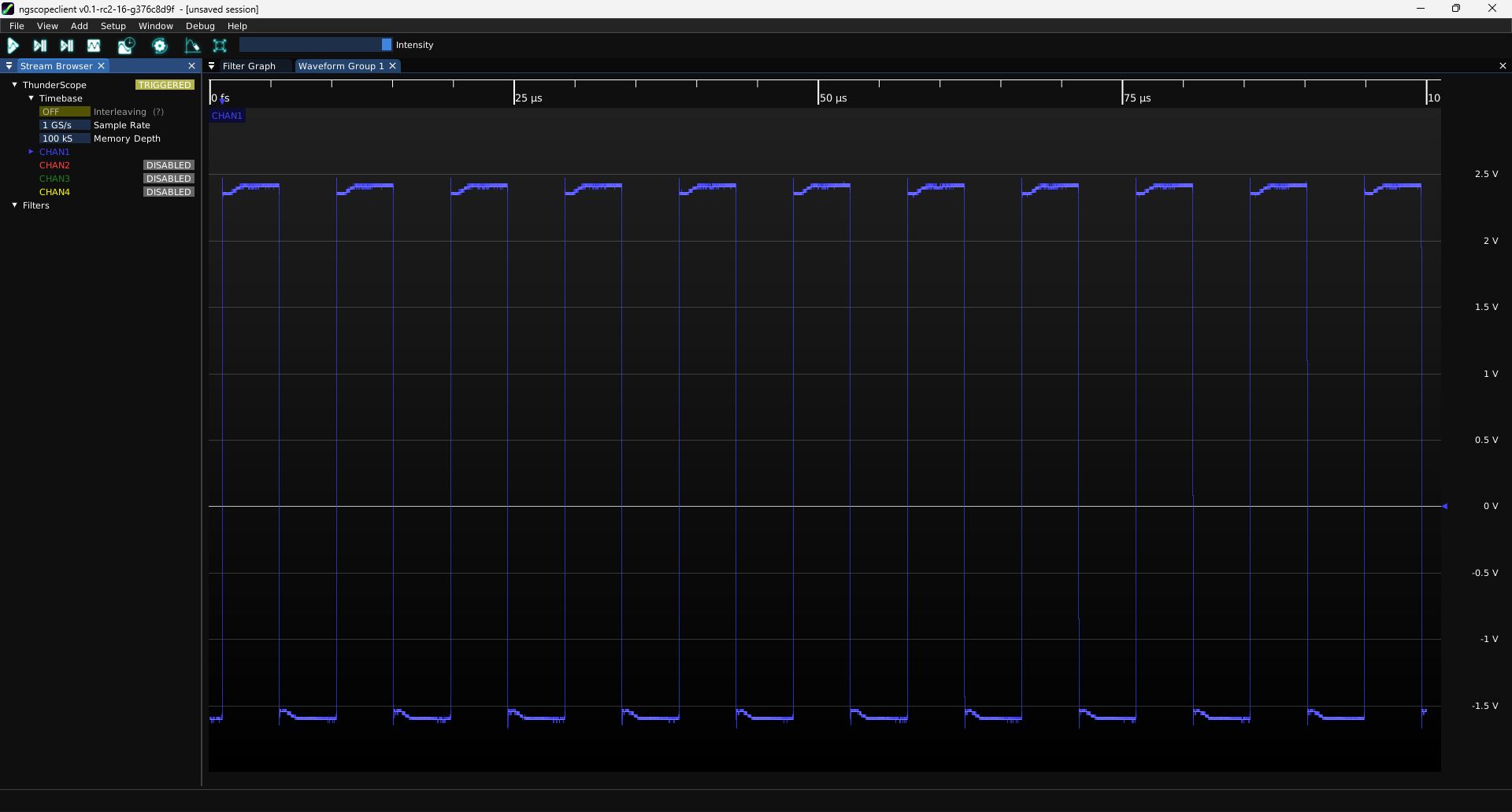
We have binary packages for Windows, MacOS (both Intel and ARM), and several Linux distros. Give it a try!
Even before your ThunderScope arrives, you can play with the built-in demo scope, load data in any of the supported waveform formats, or remote control other instruments you might have available.
So What’s Next?
We’re not done, in fact we’re picking up steam. Now that most of the major packaging and cross-platform build warts have been sorted out, we expect to be doing point releases more frequently.
First off, v0.1 had some rough edges. Surprising nobody who has ever been involved with a software project, as soon as we put it in front of a larger user-base people started reporting problems.
- A few of the Linux packages (e.g., Ubuntu 22.04) don't install properly due to the packaging scripts specifying the wrong versions of certain dependencies for the distro in question.
- We forgot to ship a portable Windows binary and only released an MSI
- The Windows version would crash when the window was minimized, but only if you had an Intel ARC GPU.
- The CI build for the MacOS Intel target would randomly fail to generate packages due to a race condition unmounting the DMG
- Importing CSV files with Windows line endings didn't work
We’re actively working on these (and other) issues and have fixes in the pipeline. The Intel ARC crash and CSV import failure are already patched in latest git commit, while the lack of a Windows portable binary was purely a release management issue (we already build this in CI and it works fine, we just didn’t upload the package when we did the release).
The current plan is to do a v0.1.1 release sometime in mid- to late-October containing fixes for these and any other major issues found in the next couple weeks. We’ll probably also squeeze in some user manual updates (there’s dozens if not hundreds of filter blocks that still need comprehensive documentation written, plus major features that aren’t mentioned in the docs in any significant detail), merge a couple of pending pull requests, and maybe try to close a few other tickets, like chasing a few last glitches on high-DPI displays.
After v0.1.1 is out the door we’ll start work on v0.2. This is going to involve a lot of back-end work and probably not too much in the way of flashy features, but it needs to happen to support future development.
The Backstory
If you haven’t been involved with the project for that long, you might not realize that libscopehal predates the ThunderScope project. It predates ngscopeclient. It predates glscopeclient, the never-properly-released OpenGL/OpenCL/GTK based ancestor to ngscopeclient that was scrapped due to poor performance and the lack of availability of key APIs (such as OpenGL 4.3 compute shaders) on MacOS. It goes all the way back to circa 2012, when I was in grad school and debugging FPGA code for my thesis on scopeclient (yes, there was a third GUI if you go deep enough into the fossil record), with no GPU acceleration at all and everything drawn on the CPU in Cairo, because I couldn’t afford an ISE ChipScope license. Software rendering wasn’t a big performance concern because the instrument support at the time was my Rigol DS1102D and an FPGA-based logic analyzer IP that dumped waveforms out to its driver over 115.2 kbaud UART.
While the project was technically open source from the start and there were BSD license headers in some of the first Subversion commits (it didn’t move to git until after I graduated), it was full of hard coded paths, lived in the same monorepo as my thesis research and several other supporting tools like libjtaghal, used a custom distributed build system, and was generally not useful to anyone other than me until I excised libscopehal and *scopeclient related code and ported the build system to CMake in late 2019 or early 2020. I think the first person other than myself to successfully build the project was some bored engineer on the Internet during the early COVID lockdowns.
As a result, there’s a lot of technical debt from engineering decisions that may have made sense at the time the code was written or architecture designed, but are no longer the right choice for the direction the project is heading today. In 2012, the vision of a GPU-accelerated oscilloscope platform that could not only render but actually do nontrivial DSP and protocol decoding on streaming sample data coming in at almost 10 Gbps wasn’t even on the radar as a possibility, much less as an explicit design goal!
Looking to the Future
There’s a bunch of internal refactoring and code restructuring that I’ve been putting off since I wanted to get a usable v0.1 out the door before going into "renovation mode" for a while. I’m gonna get into some technical details of the internals of libscopehal, which will hopefully explain some of the quirks and annoyances people have seen.
Filter Graph Topology
In the early days, the filter graph was actually implemented as a "pull-" based structure: the GUI would call Refresh() on every channel being displayed, which would then call Refresh() on every one of its inputs, etc. I’m simplifying a bit, there was a dirty bit and some locking to ensure that filters didn’t get refreshed twice, but that’s the gist of it.
We’ve since switched things around with a much more sophisticated, multi-threaded work scheduler etc., but it’s still a unidirectional graph from sink to source internally: given a filter or instrument channel, there’s no way to figure out what (if anything) is consuming its output without walking the entire graph and doing a reverse traversal from all possible sinks to see if you hit the node in question. What this means is that it’s not possible to perform an otherwise trivial optimization: have filter blocks with multiple outputs only actually use CPU/GPU resources generating those that are being displayed or consumed by another filter. Since some of these optional outputs are quite expensive to generate, we’re leaving a lot of performance on the table for some filters with infrequently used, but expensive, outputs.
It also means that it’s impossible to "delete a filter" (one of our most frequently requested UI features) because there’s no way of knowing who might be trying to use its output. You can’t gracefully disconnect a path that you don’t have any way of knowing is there!
So we’re going to restructure the filter graph to be bi-directionally linked, so that a graph edge connects source to sink AND sink to source. This will enable efficient forward traversal and relatively straightforward fixes to these currently extremely hard problems.
Reference Counting Overhaul
We currently use a homegrown reference counting system in parallel with the filter graph that conflates two different concepts: "I have a handle to this thing so it needs to continue to exist" and "I am using the waveform output from this thing".
Filters use the reference count in the same way as any other smart pointer, when the reference count hits zero the object self-deletes. But instrument channels are different - a physical channel doesn’t cease to exist just because nothing is consuming its output. Instead, when the reference count hits zero, the channel is turned off in hardware and we stop acquiring data from it when the scope triggers.
This has proved to be a huge pain for multiple reasons. To name a few:
- Manual AddRef() / Release() isn't really a smart pointer, it's still manual C-style memory management in new clothes. You can leak references and make objects that end up being effectively undeletable, or (worse) delete an object that still has something trying to use it and crash/corrupt memory.
- Since the trigger needs a pointer to its input, having a channel used as trigger source requires that it also be enabled for acquisition. On scopes (such as the ThunderScope) that do digital triggering on ADC samples, this is actually a hardware requirement - you can't trigger on data you can't see. But on scopes with analog comparator-based triggering, such as most Teledyne LeCroy models, we're forcing the channel on, which burns PC interface bandwidth, and potentially prevents interleaved capturing at higher rates for no good reason.
- All filter nodes must have something referencing them to prevent being deleted. Usually this is a waveform view or another filter, but "export to file" filters have no downstream loads except the filesystem. We currently work around this by deliberately leaking a reference to the filter, which causes it to exist forever. I think we have some hacks to do a manual free when the session is closed, but other than this export filters are like vampires: once you invite one into your session, it's impossible to get rid of.
Once we have the filter graph topology refactoring done, we can make the measurements window and waveform areas be first-class sink nodes in the filter graph. We can then periodically walk the graph to determine if a hardware channel has any loads and enable/disable it based purely on graph connectivity without using the reference count at all. (I.e., you will be able to have a handle to an inactive channel without turning it on, as long as that handle isn’t connected to the input of a graph node.) We can then special-case trigger nodes and if a channel has no loads other than the trigger, turn it on or off depending on the requirements of that specific scope model.
At this point, the only remaining reason for the reference count will be the far more conventional "keep objects around until all pointers to them cease to exist" use case. This is exactly why std::shared_ptr exists, so we can throw away our homegrown solution and use the industry standard (and have proper RAII with no manual count manipulation). It’s not Rust but it’s one step closer to proper object lifetime management.
Wrap-Up
There’s some other backend work I have planned for v0.2 that will improve performance and more importantly maintainability, and obviously there will be lots of general progress like new filter blocks, drivers for more types of instrument, bug fixes, etc.
We also have a long list of GUI side issues: we need new toolbar icons that are more visually distinct from one another (and probably make better use of color). There’s still a bunch of filter graph blocks that don’t have icons. The stream browser is a bit inconsistent in how it handles some types of channel vs others. We have some popup dialogs (e.g. for power supplies) that I’d like to remove and merge into the stream browser.
After that, who knows? There’re hundreds of open tickets and more things floating around our heads and we haven’t had a chance to prioritize what’s going to happen after 0.2 yet.
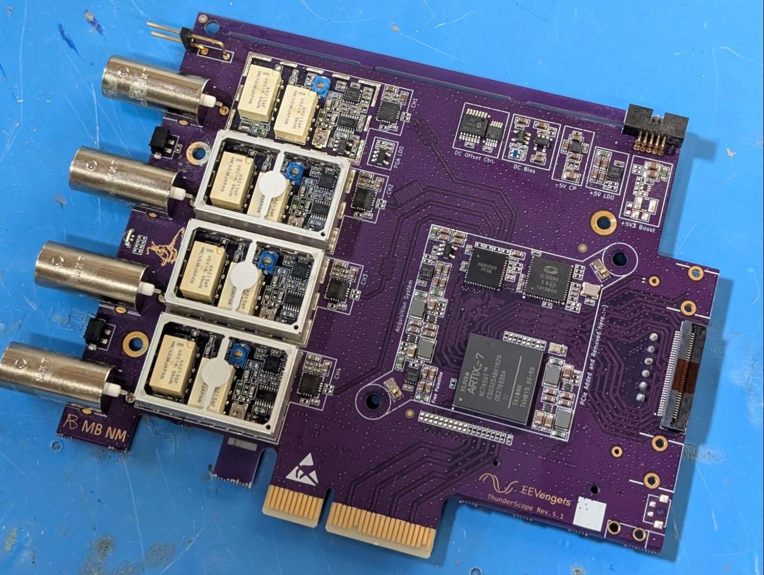
Rev 5.1 Hardware Design
Meanwhile, on the hardware side, I (Aleksa) spent a couple weeks methodically implementing all the changes I mentioned in the last update - and more importantly - documenting all of them in the github issue ECO tracker. There you can see every single component value change, every copper feature I had to move, and every new part added to the design. Thanks to @martinling for reviewing the design and suggesting some changes to further reduce the likelihood of EMI issues and noise coupling to the front end.
Rev 5.1 Hand Build
I had no trouble bringing up the one 5.1 unit I’ve built so far. For those interested, you can check out the smoke test and functional test issues.
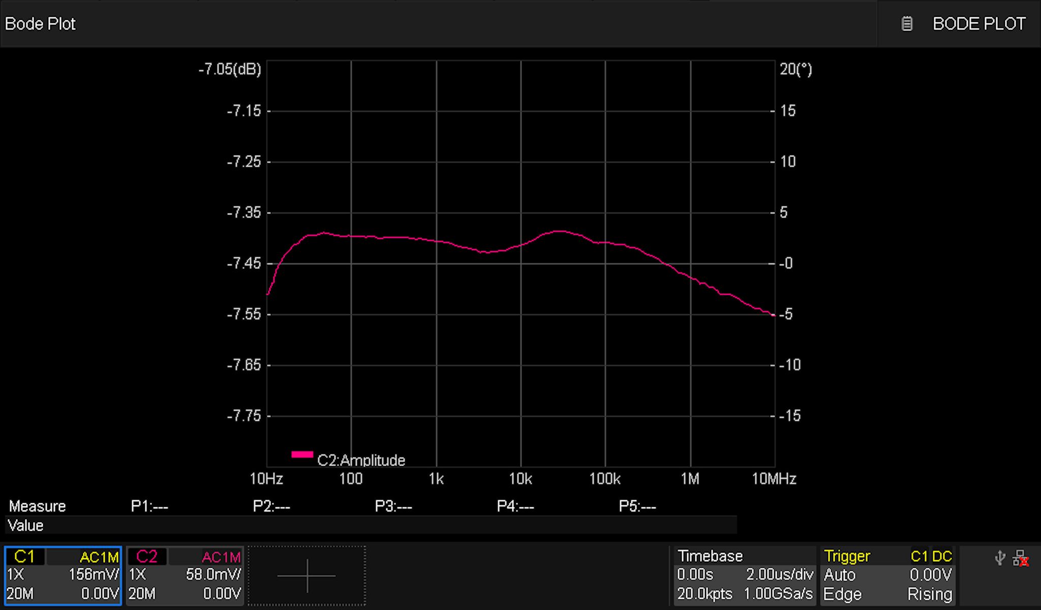
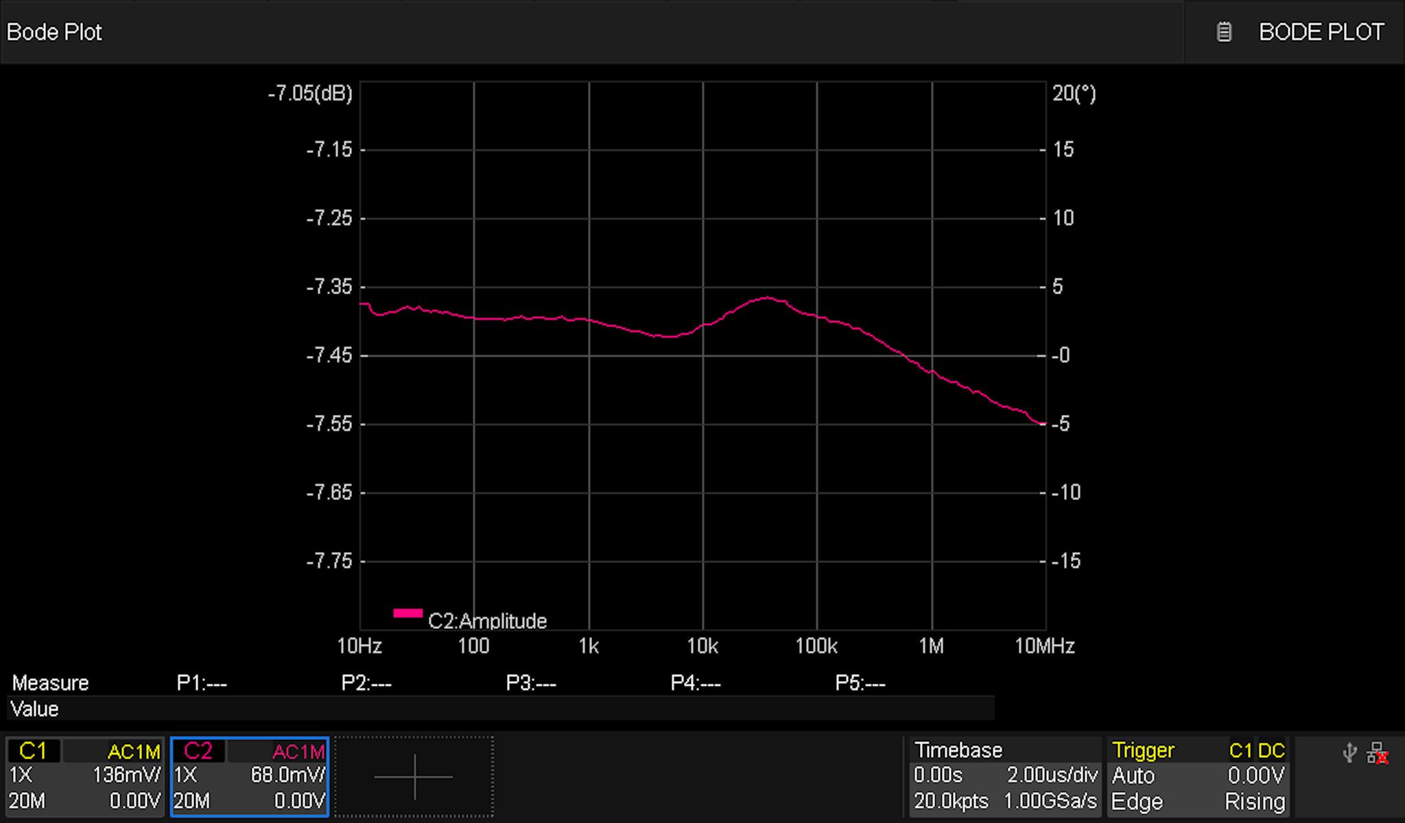
Matching the AC and DC Coupled Responses
I tuned the newly added caps switched in by the mux in order to get the responses as close as possible to each other. This is what the AC-coupled (left) and DC-coupled (right) responses look like now:
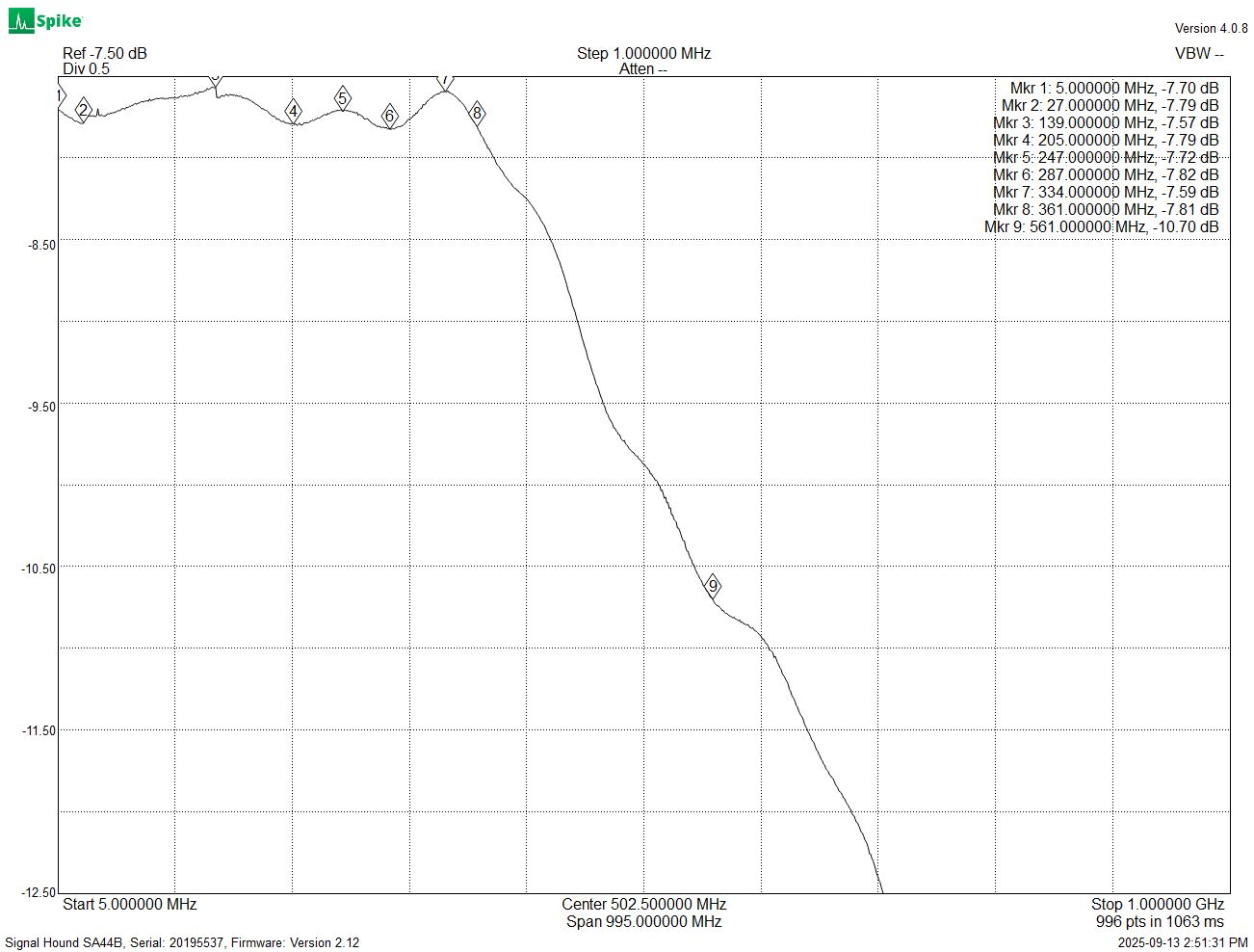
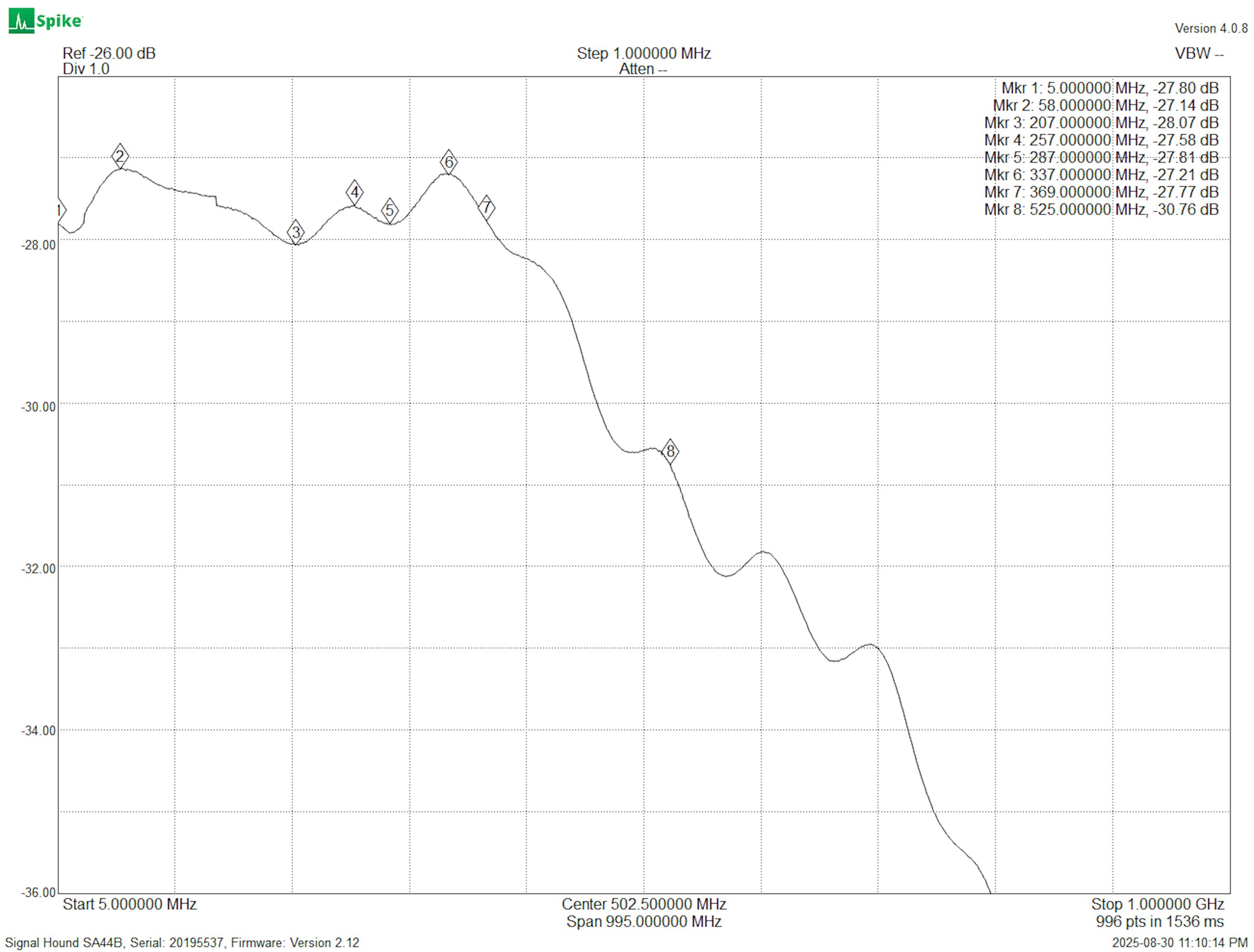
Optimizing the 1x Path High Frequency Response
At the high frequency end, I started by tuning some values on the 50 Ohm 1x path. This led to a very impressive flatness of +/- 0.1 dB out past 350 MHz, and an overall bandwidth of 560 MHz:
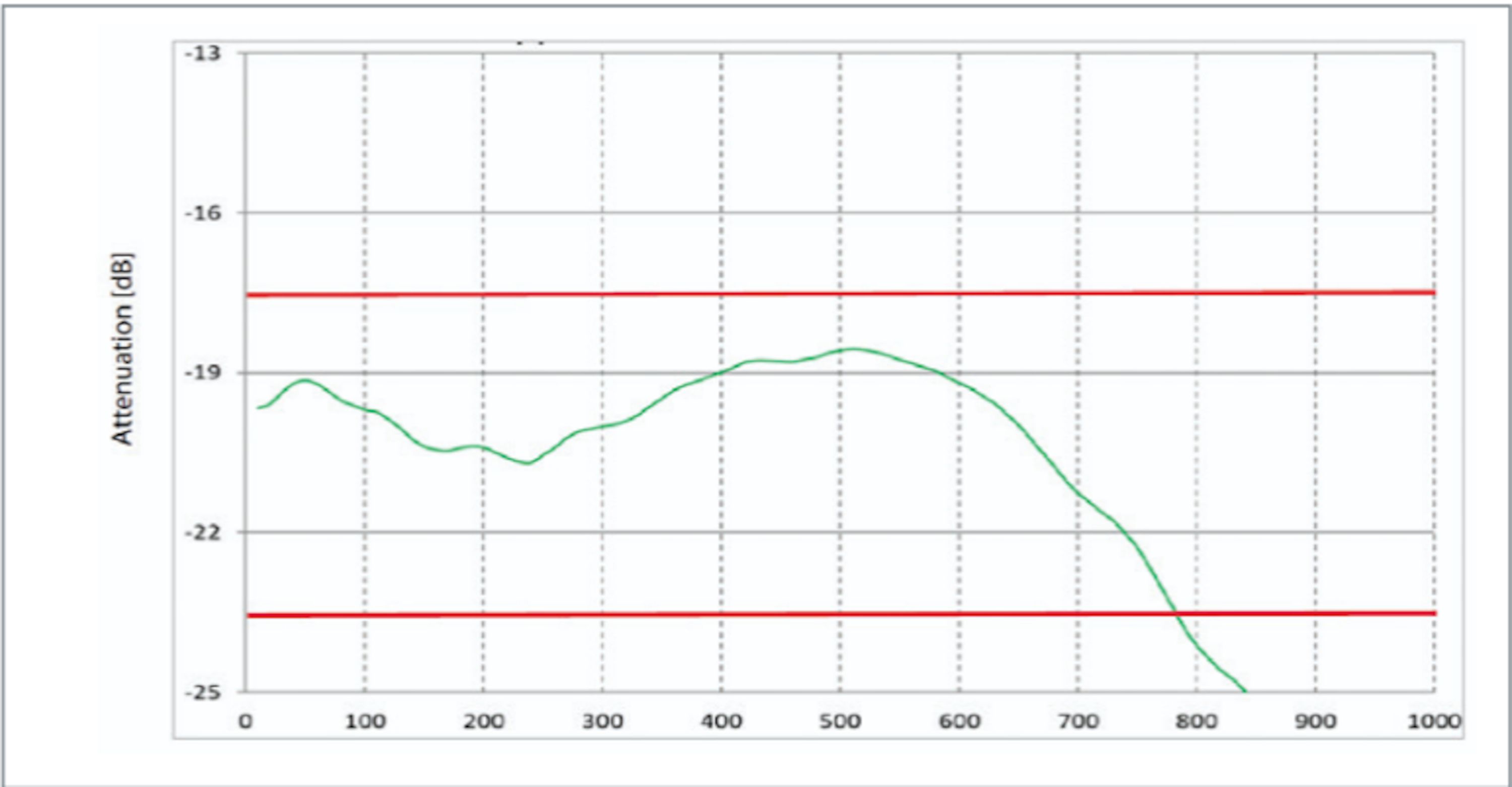
Next, I tuned the series resistor on the 1 M path to ensure the frequency response of the front end with a 500 MHz probe connected (left) matched the probe’s datasheet response (right) and resulted in a total system bandwidth above 500 MHz.
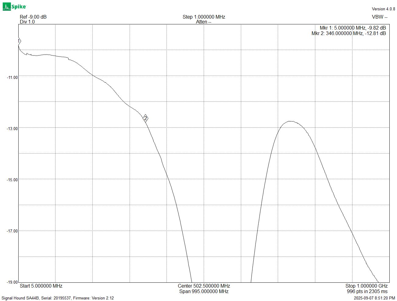
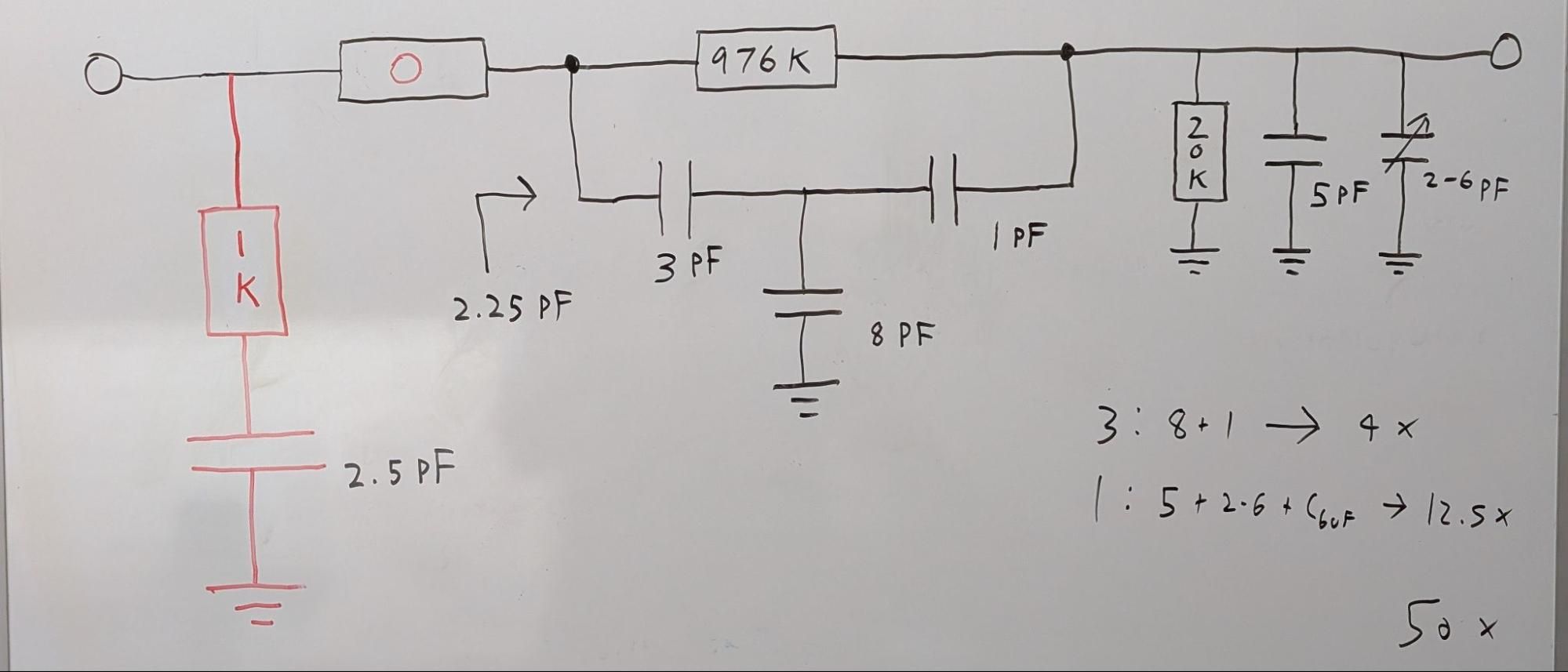
The 1M Attenuator: Final Boss of Front End Design
With everything else sorted with simple component value changes, I moved on to the attenuator. And wow, this bad boy can fit so many weird issues in it! First of all, the capacitance of this path (the 50x path) did not match that of the 1x path, so I had to tune that. It turns out the values I used to make the capacitance match completely tanked the high frequency response (50HZ response shown below):
I ended up using a series RC circuit at the input to set the capacitance for the probe compensation while not affecting the high frequency response much.
The above configuration was almost perfect, but…
An Old Foe Emerges: The 400 kHz Issue
I thought the 400 kHz issue could be ignored, since it wasn’t that bad. I was wrong, this looked awful:
You want to know the funny part? This was after I discovered something that had made this issue even worse and got it back to a normal amount of bad. So it was time to just hunker down and find a real fix!
I had two ideas:
- Add an inductor in series with the 20 k resistor, which would need to be real beefy to start doing something useful at 100 kHz
- Increase the input resistance of the attenuator, this should let that caps take over the response earlier. Basically start with a 2 M resistor to ground at the input, change the 980 k to a 1.96 M, 20 k to a 40 k.
Turns out, neither one of these worked. So I played with some simulations and found something interesting, I could make a peak in the response right where the dip was:
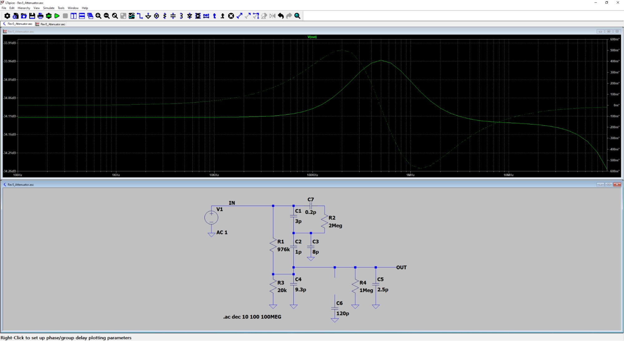
After playing around with a few different values for this other series RC circuit, I found something that worked! The dreaded 100 kHz square wave looked like this now:
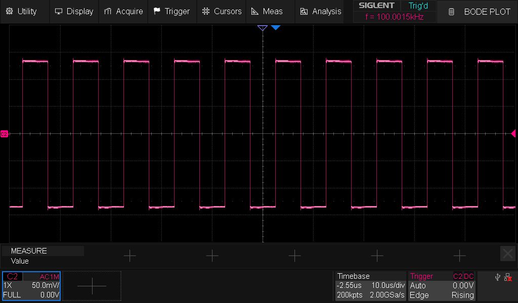
This was a bodge with a very low capacitor value, so it is crucial to validate it on an actual PCB. Here we go again!
Rev 5.2 and Production Timeline Update
Having filed all the changes into the Rev 5.2 ECO tracker, I sent this board out ASAP! All I have to do is tune the attenuator again (if needed), update the component values accordingly, and send it out to a CM to start the developer edition production run. The boards are coming back on Oct. 8th, so it should take me a week or so to assemble them, test them, and do the last tweaks to the attenuator. I expect to send the finalized design files to the CM by the end of October and will have a solid timeline through to shipment for the next update.
Test Fixture Progress
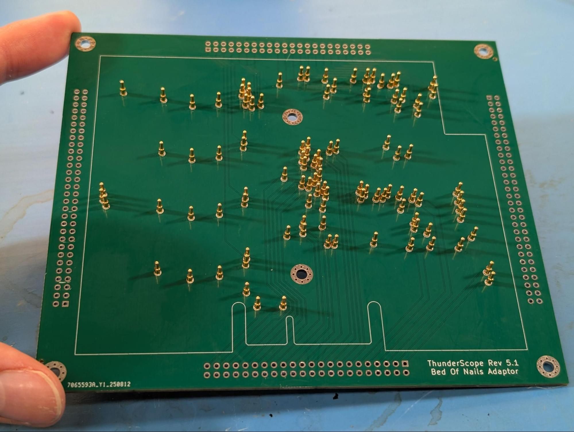
Before 5.1 came back from fab, I designed the bed of nails adaptor and later soldered all these pogo pins, right after sending 5.2 out:
While I was heads down on the attenuator issue, @akos712, a new contributor to the project, designed the other two boards in the stack that makes up this test fixture:
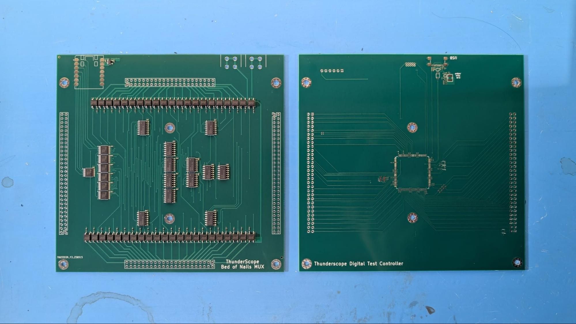
This was a huge help, all I had to do was send them out to get fabbed and (for the mux board) assembled, thanks Ákos! What’s left now is the mechanical design, firmware, and test script for the host PC controlling this whole arrangement.
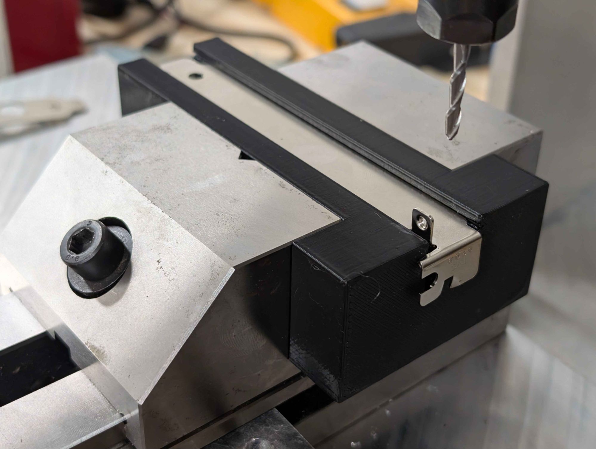
Setting up to Mill the PCIe Brackets
A friend of mine lent me a CNC mill he put together (and last ran) back in 2016. I’ve always wanted to get into CNC machining, so this was a load of fun (and frustration) to get running again.
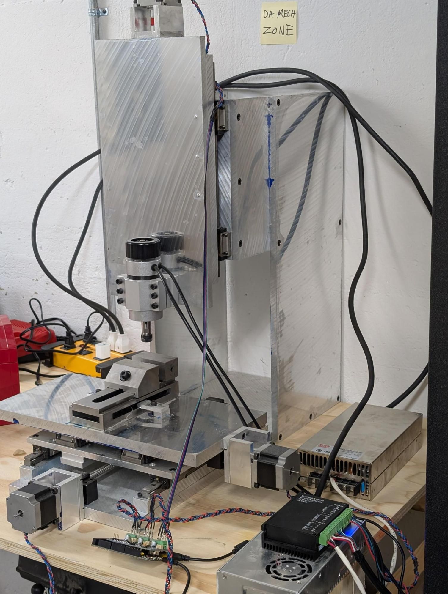
I 3D printed a nice little jig (rated four out of five jig points by a real life mechE!) and am in the process of figuring out how to go from a 3D model of the bracket to g-code that this mill can understand.
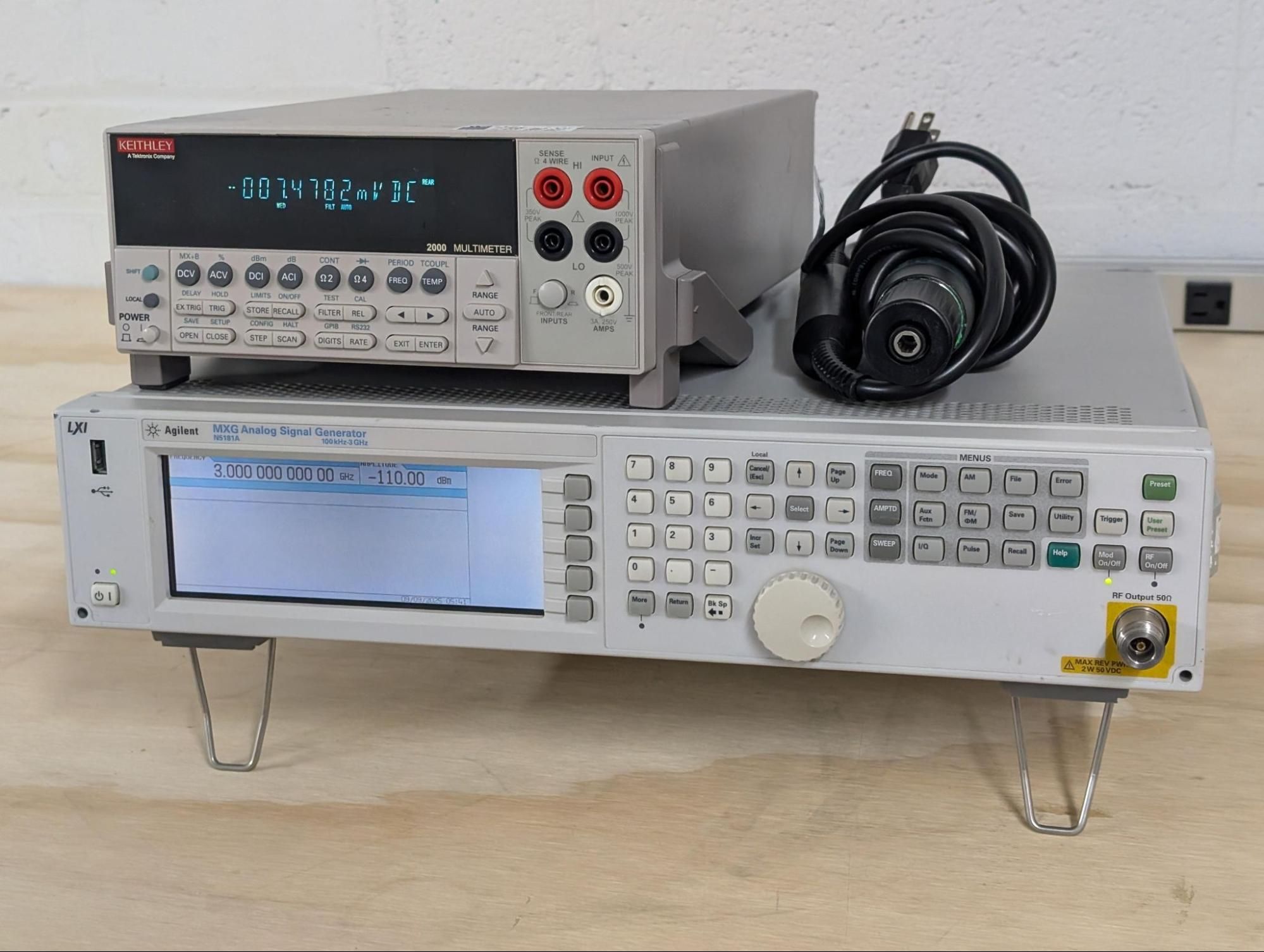
Test Equipment For Testing Test Equipment
A certain anonymous crow from the test equipment darkweb has lent us some equipment to make production much easier on us! Thanks, you know who you are…
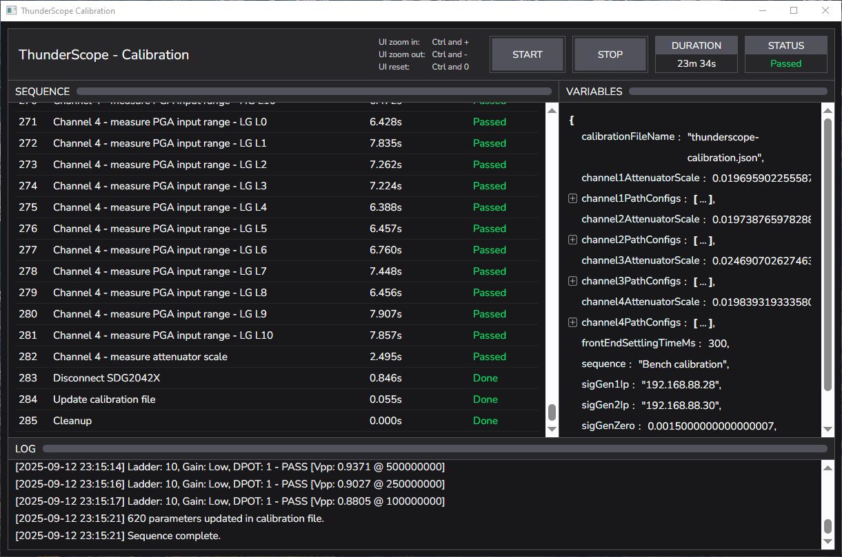
Calibration and 12-Bit Mode
Just as a little teaser for a future guest author’s update, Mark (@macaba) has made an incredible calibration utility with countless parameters to correct for every little thing that could affect gain or offset on the hardware. In addition, Nate (@NateMeyer) has added an API to allow these parameters to be saved onto the device, so there’s no need to carry your cal file over when using your ThunderScope on a new host. Nate is also working on the gateware changes needed to implement 12-bit mode!
Well, that was a jam-packed update. I’ll let you all know how Rev 5.2 goes by the end of October, see ya then!
-Andrew Z and Aleksa B