Project update 8 of 8
A Tutorial for Using BlueIODevin for Mobile Applications
by Jonathan AlbrechtSetup Overview
Fig. 1, below, illustrates the setup for using the BlueIODevin app to remotely interact with the I2C or SPI interface of a target device via a BlueIO832Mini board. Here, the app is Bluetooth-paired with the BlueIO832Mini board, then this board is connected to the I2C or SPI interface of the target device.
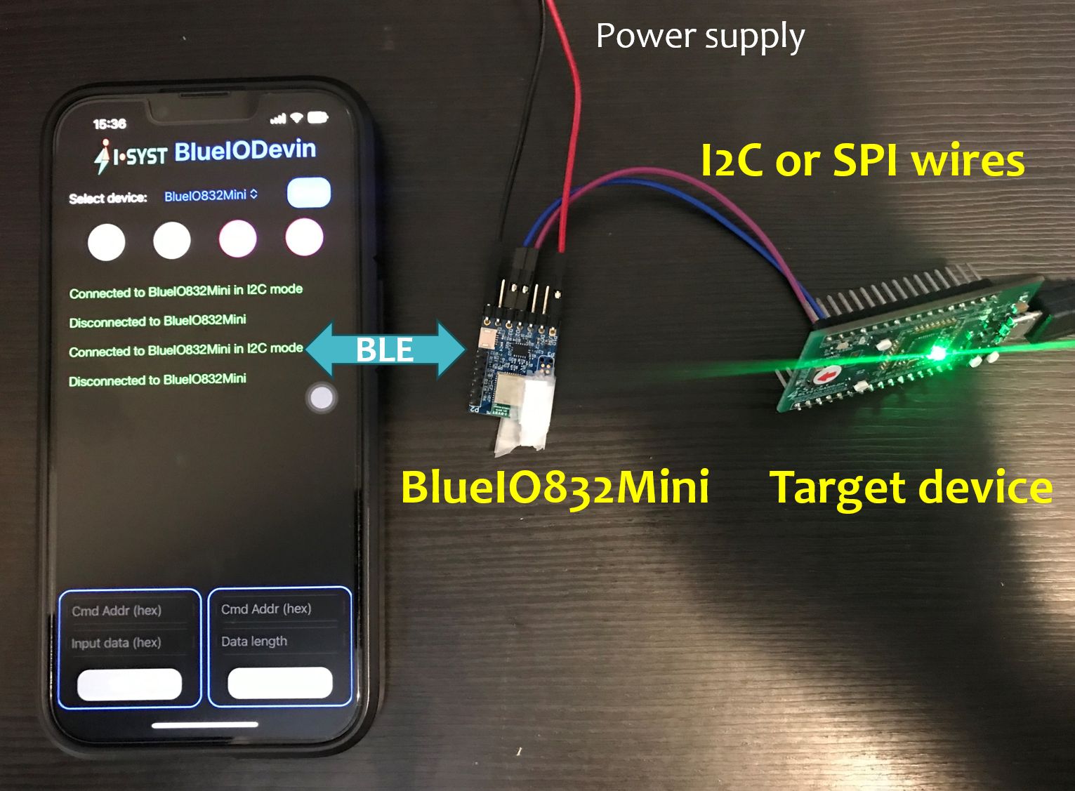
Fig. 2 shows the main user interface (UI) of the BlueIODevin app:
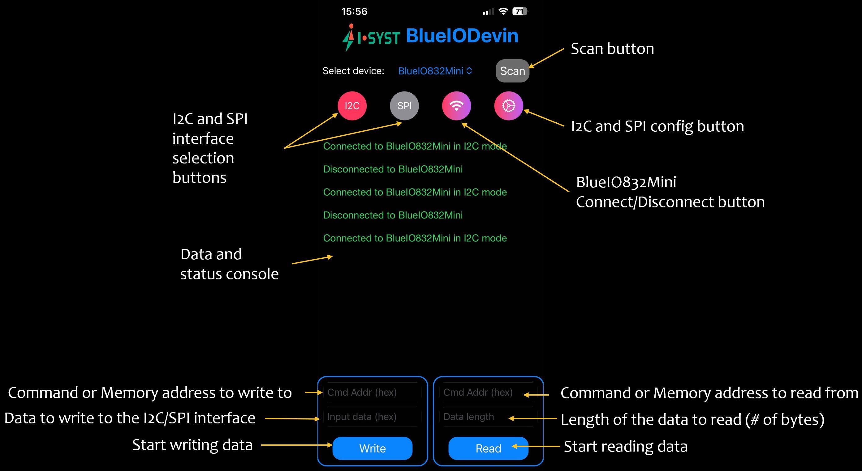
Before the app can interact with the I2C/SPI interface, we need to pair it with the BlueIO832Mini. The steps for that are as follows:
- Connect the BlueIO832Mini board to the I2C/SPI interface of the target device. Note that the BlueIO832Mini's pins are app configurable.
- Supply power to the BlueIOMini832 and the target device.
- Press the "Scan" button to search for all available BlueIO832Mini board.
- Select the desired BlueIO832Mini and press tge "Connect/Disconnect" button to pair the app with this board.
- Press the "I2C" or "SPI" button to select the appropriate I2C/SPI interface.
- The connection status and current working mode (I2C/SPI) are displayed on the Data and Status console.
Now, the app can send and read data to and from the target device’s I2C/SPI interface.
The "Write" sub-window allows us to write a series of hexadecimal bytes along with a proprietary I2C/SPI command or memory address (hexadecimal format) to I2C/SPI interface.
The "Read" sub-window allows us to read a series of bytes, i.e., data length, along with a proprietary I2C/SPI command or memory address (hexadecimal format) from I2C/SPI interface.
Examples of Using BlueIODevin App to Read and Write Data From/To An I2C Interface
Here’s an illustrative example of reading and writing data from and to an I2C interface. In this case, the target device simply acts as a memory repository where data can be accessed via I2C interface. The memory was initialized with the following bytes, starting from memory index 0.
(hex) 00 01 02 03 04 05 06 07 08 09 0A 0B 0C 0D 0E 0F
Fig. 3 shows an example of reading ten data bytes from the target device, starting from memory offset one.
After pressing "Read" button, the app Data and Status Console displays the data obtained from the I2C interface. As can be seen, the obtained data is
01 02 03 04 05 06 07 08 09 0A
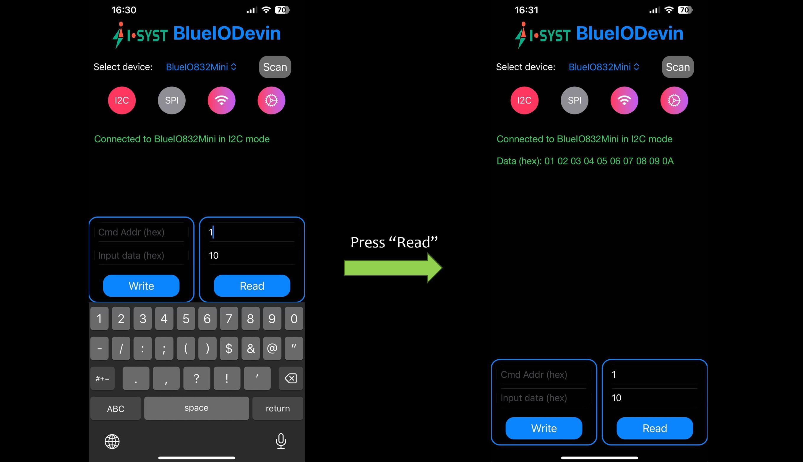
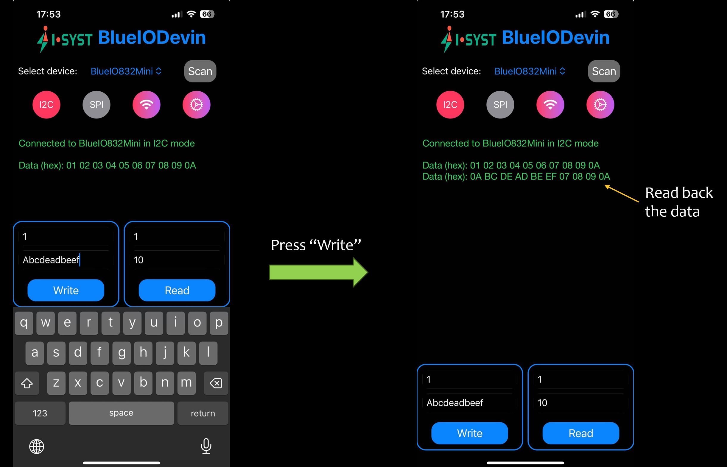
Fig. 4 shows an example of writing a value, 0xABCDEADBEEF, to memory, starting from memory offset one.
Press the "Write" button and the data will be written the target device. We can read back from the target device memory to verify the app has successfully written the data to the target device, as shown in the right of Fig. 4.
The read and write steps regarding SPI interface are similar.
Configure I2C and SPI Interface Parameters
Thanks to BlueIO832Mini’s firmware and the BlueIODevin app, users can configure I2C and SPI interface parameters for their particular needs. By pressing "Configure" button (see Fig. 2 above), users enter the configuration UI as shown in Fig. 5, below.
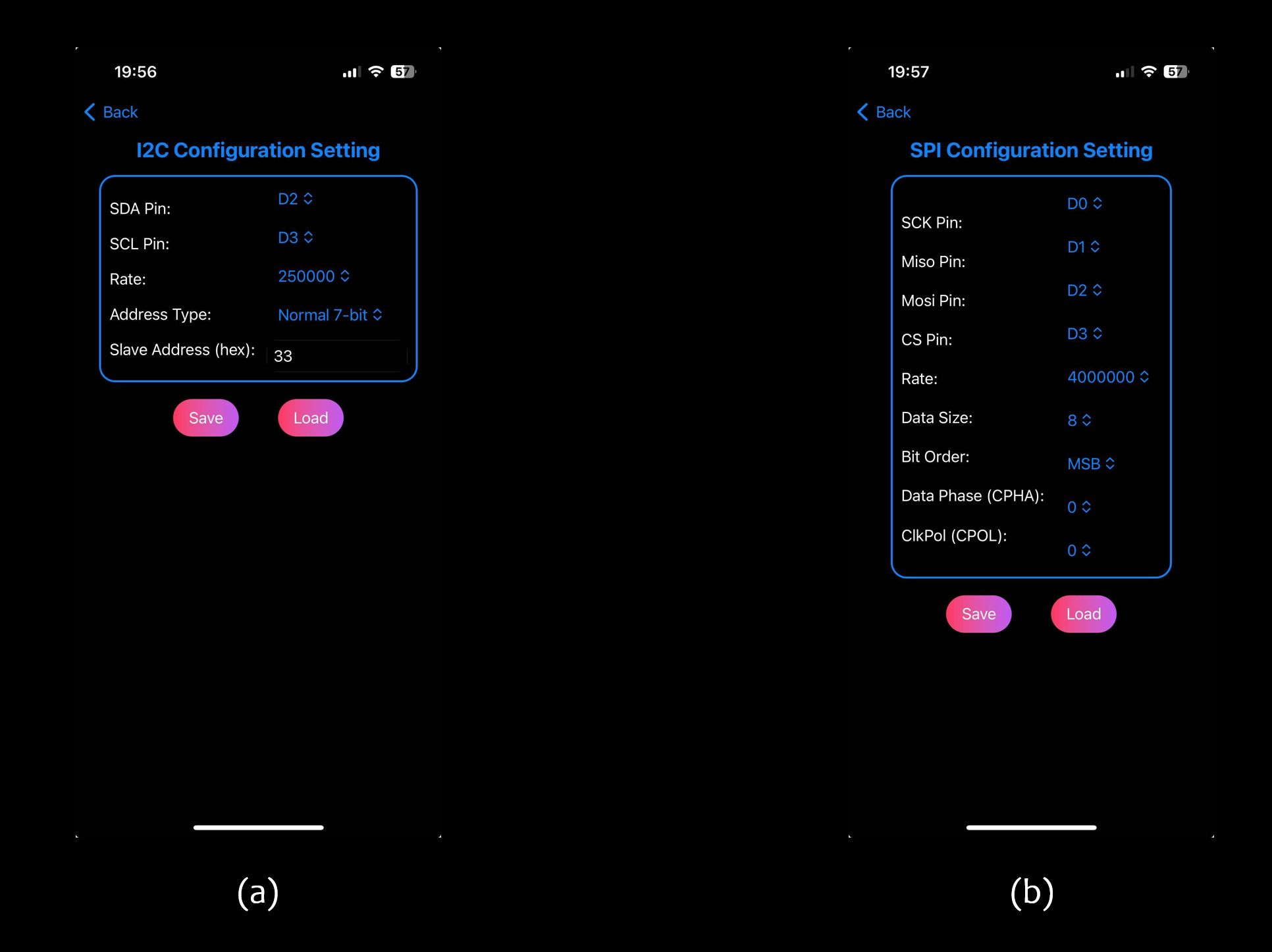
The configurable I2C interface parameters include:
- SDA pin: pins D0-D5
- SCL pin: pin D0-D5
- Data rate: 100 KHz, 250 KHz, 400 KHz
- Address type: 7 bits (normal address), 10 bits (extended address)
- Slave address: address of the target I2C interface
The configurable SPI parameters include:
- SCK pin: pins D0-D5
- MISO pin: pins D0-D5
- MOSI pin: pins D0-D5
- CS pin: pins D0-D5
- Data rate: 125 KHz, 250 KHz, 500 KHz, 1 MHz, 2 MHz, 4 MHz, 8 MHz
- Bit order: MSB and LSB
- Data phase: CPHA = 0, CPHA = 1
- Clock polarity: CPOL = 0, CPOL = 1
We hope you enjoy playing with the BlueIODevin App!
Thanks so much,
I-SYST team