Project update 3 of 4
Getting Accurate Orientation Representation With Sensor Fusion
by Tomer AbramovichGetting accurate orientation representation is not a trivial task. Thanks to advances in MEMS technology, however, we now have access to many cheap motion sensors. And placing various types of sensors on a body gives us several different ways in which to measure that body’s orientation in 3D space. That "body," in our case, is the Bluetera II. :)
3-Axis Gyroscope
The raw measurement of a gyroscope is the rate of rotation, in degrees per second, on each axis. Integrating those measurements over time tells us how much our angle has changed relative to where we started.
3-Axis Accelerometer
The raw measurement of an accelerometer is the acceleration acting upon each axis, in units of G, where 1 G is approximately 9.82 m/s². We can measure the absolute orientation of Bluetera II, relative to the earth’s gravity, by using some simple trigonometry. Imagine a plane defined by the X and Y axes, and we are calculating the angle between it and earth’s constant gravity vector.
3-Axis Magnetometer
The raw measurement of a magnetometer is the magnetic field strength on each axis, in units of mG (milligauss). In a similar way to the accelerometer, we can use the magnetometer to calculate an absolute orientation.
"The Catch"
In an ideal world, a gyroscope alone could provided an accurate measurement of the relative orientation of our Bluetera II. By constantly integrating the rate of rotation on each axis, as measured by the gyro, we would know our exact orientation in 3D space relative to our initial orientation. Unfortunately, we don’t live in an ideal world, and our sensors have some inherent noise in their measurements. If we naively integrate our gyro samples, we will accumulate an error, one that will grow larger with time. This error is dubbed "gyro drift".
OK, so what about that accelerometer? As stated above, the accelerometer can be used to calculate the absolute orientation of our Bluetera II, because it has access to a constant, known force that always acts in the same direction. There are two problems, however:
The orientation you get from the accelerometer alone would not be complete. Imagine again the plane defined by the X and Y axes (for Bluetera II, this plane can be represented by the PCB itself). We can calculate this plane’s angle relative to the vector of earth’s gravity, but we cannot determine our rotation around the Z axis!
While moving, our accelerometer reading would be affected by other accelerations that might act upon it. That interference could negate or otherwise obstruct the Earth’s gravity effect. Imagine, for example, dropping your Bluetera II from the roof of a building. While in freefall, the accelerometer would measure zero acceleration on all axes. The Bluetera II would "feel" like it was in space! And then it would hit the ground.
We don’t want you to damage your Bluetera II by carrying out the experiment described above, so…we did it for you:
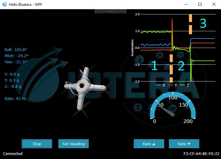
The corresponding acceleration graph is divided into three parts:
- Holding Bluetera II (almost) still – You can see the constant 1 G on the Z axis
- After releasing Bluetera II – It is now in freefall, and the accelerometer reads approximately 0 G on all axes
- Once Bluetera II hits the (soft!) ground – The accelerometer again reads a constant 1 G, but now it is spread across different axes as it landed in a random orientation
Finally, in terms of calculating absolute orientation, a magnetometer has properties similar to those of an accelerometer. Unfortunately, it also faces the same challenge: knowing the angle of a plane relative to a constant vector (in this case the Earth’s magnetic pole) but not being able to measure the rotation of that plane. In addition, nearby electrical currents and ferro-magnetic objects can affect the measurements of a magnetometer, which must therefore be calibrated for it’s environment.
The Sensor Fusion Algorithm
The purpose of this algorithm is to fuse the measurements of various sensors—to compensate for the weakness of each by leveraging the strength of the others.
Let’s start again with the gyro. We integrate its measurements, which give us our relative orientation, but those measurements lose accuracy over time because of gyro drift. If we were to place our Bluetera II on a table and wait…we would see the orientation of our motionless board slowly change. Not ideal.
So we add an accelerometer to the mix as a way of compensating for that drift. Now we have an orientation representation that does not drift along the roll and pitch axes! (This is called "6-axis sensor fusion" because it combines a 3-axis gyroscope and a 3-axis accelerometer). But our yaw axis can still drift over time. If we put our Bluetera II back on that table, we would see that the roll and pitch orientations are fixed, but the yaw would still change over time. More work to do…
Finally, we add a magnetometer to fix the yaw drift, thus providing a 9-axis fusion of all three sensors. Now if we put our Bluetera II back on the table, its orientation measurements won’t change at all!
Bluetera II’s Output
By default, Bluetera II outputs a quaternion. A quaternion is a mathematical entity that can represent rotation in 3D space. It has certain advantages over good old fashioned Euler angles, including better interpolation and no gimbal lock. The quaternion produced by Bluetera II is the result of a 9-axis sensor fusion algorithm that combines the outputs of an ICM-42605 (3-axis gyroscope and 3-axis accelerometer) with the output of an LIS2MDL (3-axis magnetometer). The specific algorithm used is the open source Madgwick sensor fusion algorithm.
Bluetera II can also be configured, using Protobuf commands over Bluetooth, to output the raw measurements of its individual sensors (or various combinations of those measurements).
SDK Utility Functions
So now that we have a platform capable of producing very accurate representations of its own orientation, what’s next? We are currently developing some utility functions to help with the processing of that motion data: calibration functions and ways to map local (Bluetera II) coordinate systems onto "target object" coordinate systems (see below), among others.
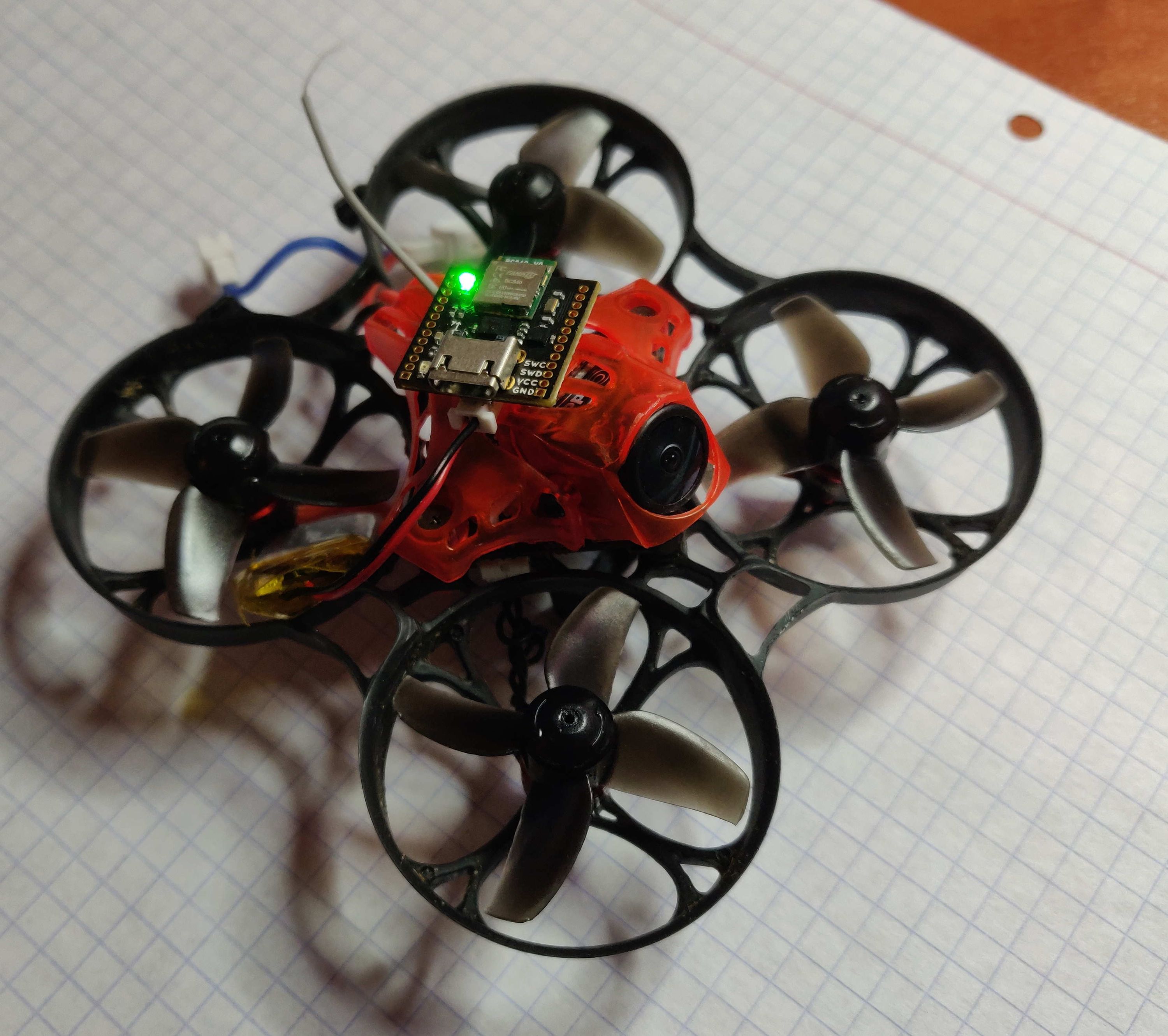
Aligning Bluetera II’s coordinate system with that of the quadcopter shown above is not trivial. You cannot simply rotate the former on a single axis until it matches the latter. Fortunately, our SDK provides a utility that will help you. (More on than in a future update.)
Please feel free to comment here, or using our GitHub issue tracker, if you would like to suggest an SDK utility function that you or someone else might find useful!