Project update 73 of 83
Field Report: A bit pattern generator aligned with the SDR data stream
by Andrin DSubmitted by Andrin Doll, a researcher at the interface between magnetic resonance and technology who discovered the LimeSDR during his postdoc at CEA Saclay in France.
The LimeSDR devices provide a versatile transceiver that suits a number of applications that require reception and transmission at radio frequency. Of particular interest is the use of this low-cost SDR in scientific research and academia, as the frequency range is adapted to a number of experimental techniques. However, in order to incorporate an SDR into such experiments, synchronization with external devices is often crucial. In my case, the technique of interest is magnetic resonance with either nuclear spins or electron spins. I am pursuing these techniques within my postdoc fellowship at the CEA Saclay in France funded by the Swiss National Science Foundation (grant #177732).
In its basic version, the LimeSDR can synchronize its reference frequency to an external reference and synchronization between the TX and RX streams is facilitated by timestamps. Eight GPIO pins are available that can be controlled by the software. However, it is not possible to tie the GPIO state to the data stream, which would be required for basic synchronization with external devices. To achieve this, an augmented firmware has been developed by Prof. C. Michal, also in the context of magnetic resonance spectroscopy. In his firmware, the timestamp in the SDR is reset when a specific GPIO pin gets set to high. The LimeSDR can thus be triggered by an external device using this modified firmware.
In my application, the situation is reversed: It is the LimeSDR that triggers up to four external devices. In essence, I modified the FPGA firmware such that four GPIO outputs represent four bits of the TX stream. A TX data packet thus consists of 16 bits in total: 12 bits for the DACs and 4 bits for the GPIO. Importantly, the LimeSuite API already implements streams with 16-bit data, which is natural given the bus width of the USB interface. Accordingly, there was no need for me to make any changes in the API. One only needs to select the 16-bit data format in the API to avoid packaging three 12 bit samples into two 16 bit samples. Moreover, when I studied the FPGA firmware, I realized that the data actually remain 16 bits for quite a while. There are only a few instances before the data is sent from the FPGA to the LimeSDR where the four bits are normally discarded (look for ‘inst2_fifo_q’ in tx_path_top.vhd). In the modified firmware, these four bits remain together with the DAC data up to the double data rate (DDR) bus at the output and are then routed to the GPIO pins.
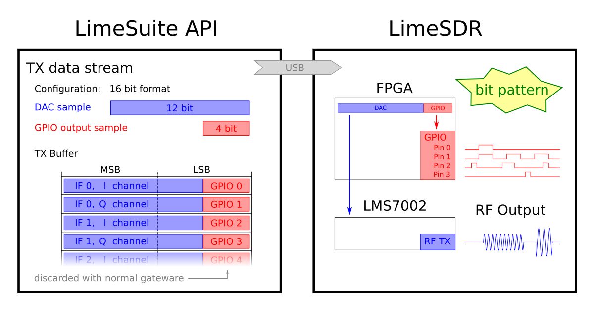
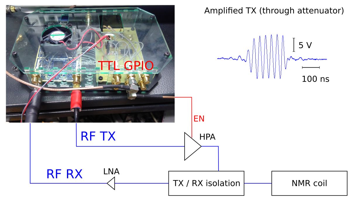
A notable detail is that the stream data for the DACs are complex I/Q pairs. As a result, the sampling rate of the GPIO outputs will be twice the sampling rate of the SDR, unless you interpolate your TX data downstream in the TSP to a faster rate. I tested this both on a LimeSDR mini, where I implemented it first, and on a LimeSDR USB. With the LimeSDR USB, one needs to take care of all the MUX positions in txiq.vhd, so that the alignment is preserved across the different MIMO modes. In order to ease the distribution of the GPIO signals, I made a companion board that buffers the signals to 5 V TTL level with low-impedance line buffers. Indeed, the principal challenge at this point was to acquire the details on what’s going on in the API/firmware. At the same time, this is also the main advantage of the MyriadRF project’s open source nature. I was able to learn a lot from going through the API and FPGA code.
I then went to the lab with the augmented LimeSDR USB and successfully set up two experiments. The details of these experiments are beyond the scope of this field report and will be detailed in a scientific publication, together with the underlying source code and firmware. Here, I will just give a rough sketch.
Both experiments are built around an RF coil that is tuned to the desired frequency and contains the sample. The RX and TX channel are both connected to this coil (via external amplifiers) and isolated from each other by passive means. The first experiment is a basic pulsed nuclear magnetic resonance (NMR) experiment. In this experiment, a strong and short RF pulse is required, namely a few tens of volts for few microseconds. After this pulse, a rather weak nuclear induction signal can be captured by the RX. The frequency of the experiment is determined by the magnetic field applied to the spins. In my case, the field was 0.7 T, which prescribes a frequency of 30 MHz. The GPIO was used here to activate the high power amplifier during the pulse duration – otherwise, the output noise from the power amplifier would swamp the RX during reception. In other words, passive isolation is often insufficient for this type of experiment and the GPIO provides the time-critical trigger for active isolation.
The second experiment is a basic continuous-wave (CW) electron spin resonance (ESR) experiment. Here, I applied a field of 5 mT to the sample, which sets the experiment’s frequency to 150 MHz. However, the magnetic field in CW ESR is not static, it wobbles slightly with a modulation frequency in the kHz range. Thanks to this wobbling, the spin signal appears on sidebands around the 150 MHz carrier that is incidental on the sample. Traditionally, excitation and detection of this wobbling involve a lock-in amplifier at the modulation frequency. When using the LimeSDR for this, the missing part is the modulation frequency in the kHz range. One can easily add a sine-wave generator that shares the reference clock with the LimeSDR. However, this only works to a limited extent, since the phase between the external sinewave and the SDR data stream will be different for each time the experiment is run.
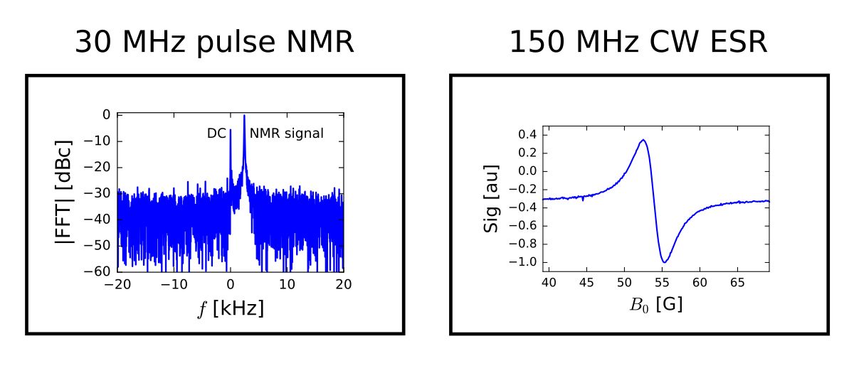
Accordingly, I use a GPIO pin to generate a square wave of 105 kHz, which always has the same phase as the SDR data stream (up to a phase shift of 180 degree that can arise due to the clock management within the LimeSDR). Using opamps and extensive low-pass filtering, the square wave is transformed into a sine with the proper characteristics for the experiment. As a result, I can extract the spin signal on the modulation sideband. Overall, the GPIO was here used to synthesize a kHz oscillator with its phase tied to the SDR stream. It is actually not yet working perfectly, as I always see a small sideband around the carrier. This is most likely due to unwanted coupling between the kHz square wave and the RF. For the moment, this adds a constant offset to my spectra, which is acceptable (and actually allows the determination of the phase of 180 degrees mentioned just above). In the longer run, one could elaborate on this further. A more versatile, better performing design could be achieved with an external DDS that runs on the LimeSDR reference clock. By resetting the DDS phase with a GPIO output, a reproducible phase relation could be established.
Did you do something cool with a Crowd Supply project? Let the world know by submitting your own Field Report!