Mar 23, 2021
Project update 2 of 12
Pinout Diagram & I²C Library
by Nikunj BhagatFor my first weekly update, I have prepared a pinout diagram to help clarify how NeuroStimDuino connects to an Arduino MEGA or Due:
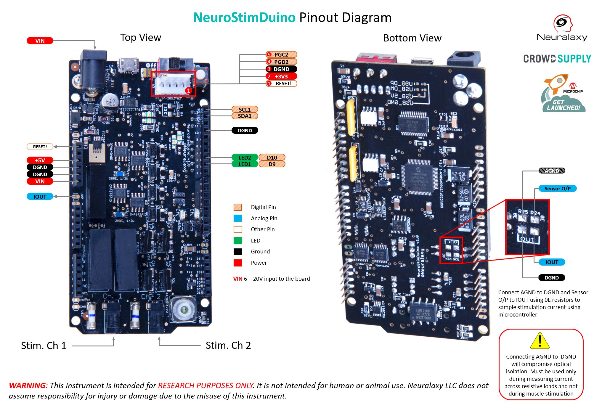
(Click to expand)
I would also like to introduce the I²C library that you will use to to configure and control the stimulator.
I²C Library for NeuroStimDuino
NeuroStimDuino can be controlled by an external microcontroller such as Arduino Due or Mega using the I²C interface, with NeuroStimDuino acting as I² peripheral device (default address = 0x1A). A list of Opcode-style commands can be used to configure different parameters of stimulation waveform such as frequency, amplitude, etc. Each I²C message should have following structure:
- Byte 0 indicates the number of bytes that will be transferred
- Byte 1 is the Opcode command from the instruction set below for the stimulation parameter that will be modified
- Byte 2 is the channel number (1 or 2) that will written to or read from
- Byte 3 is the LSB byte of the value written
- Byte 4 is the MSB byte of the value written
Instruction Set
| Instruction | Address | Description | Acceptable Range |
|---|---|---|---|
| AMPL | 0x01 | Change stimulation amplitude | 0 - 127 (Digital potentiometer count) |
| FREQ | 0x02 | Change stimulation frequency | 1 - 100, Unit: Hz |
| DURN | 0x03 | Change pulse-duration of the cathodic pulse. | 0 - 2000, Unit: uSec. |
| IDLY | 0x04 | Change inter-phase delay | 0 - 255, Unit: uSec. |
| DELY | 0x05 | Delay to the start of the stimulation pulse in each cycle | 0 - 1/(stimulation frequency), Unit: mSec. |
| SYMM | 0x06 | Generate symmetrical or asymmetrical stim waveform | 1 = Symm.; 0 = Asymm. |
| ADDR | 0x07 | Change 7-bit I2C address | 0x08 - 0x77; 0x80 - 0xFF |
| SAMP | 0x08 | Sample current from active channels | - |
| READ | 0x09 | Read value of register | - |
| RSET | 0x0A | Reset NeuroStimDuino to default register values | - |
| EOFF | 0x0F | Generate Emergency Off condition | - |
| STIM | 0x10 | Start stimulation on channel 1 or 2 for specified duration | 0 - 255, Unit: Sec. |
| STOP | 0x12 | Stop stimulation on channel 1 or 2 | - |
| ENAB | 0x14 | Enable or disable a stim. channel | 1 = Enable; 0 = Disable |
| IDLE | 0x20 | Idle | - |