Project update 3 of 10
The SYZYGY Origin Story (Part II)
The SYZYGY standard was a response to customer demand for a flexible, well-defined, modern interface between an FPGA and off-the-shelf peripheral modules.
Connector Choice
In our search for an appropriate connector, we explored connectors from Samtec, Molex, Hirose, and others. We considered thru-hole, surface mount, and even edge-card interconnects. We wanted something readily available, low cost but capable of hitting our performance targets. We also liked the idea of an available cable option and a screw mount for applications where mechanical ruggedness is important.
We finally settled on Samtec. Without sounding too much like an advertisement, their extensive line of connectors met all of our requirements and we were pleasantly surprised with the cost of the cable options considering the performance provided. Because of our long history using Samtec connectors, we were also very familiar with the parts, documentation, supply chain availability, performance, cost, and reliability. Since HSMC and FMC both utilized Samtec connectors, we also knew there was widespread familiarity within the FPGA community.
Connector Pinout
The greatest source of contention and debate has undoubtedly been the decision to separate standard and transceiver ports and use incompatible connectors for the two interfaces. There is a certain elegance that comes from having a unified connector — one CAD drawing to make, one part on the BOM, simplified supply chain, and less documentation are some of the obvious advantages. There are also disadvantages to the unified connector approach. All but the highest end peripherals will leave most pins on the connector unused, wasting a precious FPGA resource. The larger connectors necessary to satisfy the total pin requirements also result in larger boards at higher costs.
Both HSMC and FMC opt to include transceiver pairs on a single unified connector. But they’re also in pursuit of slightly different goals, as they strive to offer a single connector compatible with any peripheral an engineer could dream up. We wanted something small and usable for single-purpose peripherals. We also wanted something that would tread lightly when it comes to FPGA pin usage, allowing designers to optimize FPGA pin economy across the entire deployment of carriers and peripherals.
Here are some of the goals we tried to achieve and the considerations that led to decisions in the corresponding area.
- Small Connectors - Transceiver pairs are completely unused on standard peripherals and most peripherals today would be classified as standard peripherals. Including transceiver pairs on a unified connector means lots of "dark" conductors and that means added cost.
- Low Cost Connectors - Finer pitch connectors with missing conductors offer better signal integrity but are a bit more expensive. Since most peripherals would be standard peripherals, all of these would carry the added expense of a more expensive unified connector.
- Low Cost Cables - The twinaxial cables provide incredible signal integrity for impedance controlled differential pairs but their added expense would be wasted for the majority of standard peripherals.
- FPGA Pin Economy - We observed that transceiver peripherals generally consumed fewer standard I/O than transceiver peripherals and obviously standard peripherals required no transceiver pins. So a unified port format would invariably waste FPGA pins.
With the above goals in mind, we made the decision to separate the standard and transceiver connectors. With the pin count requirements we compiled from our list of typical peripherals, we found that a 40-pin connector would meet our needs for both standard and transceiver peripherals. This allows SYZYGY to support the vast majority of peripherals previously only supported by FMC and HSMC with a connector footprint about the size of a PMOD connection.
Photos!
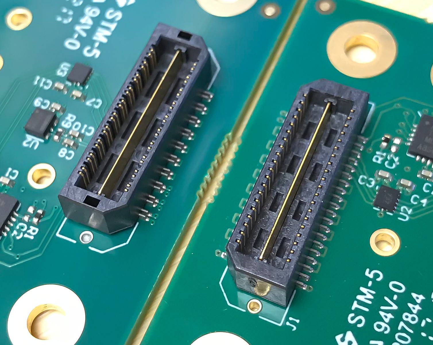
Here are the two peripheral-side connectors head-to-head for comparison. As you can see, they are the same length, but the SYZYGY Standard connector is lower density (0.8mm spacing) than the SYZYGY Transceiver connector (0.5mm spacing). Additionally, every third pin of the transceiver connector is removed to provide better crosstalk isolation between conductor pairs. The higher density makes up for the missing conductors to yield identical pin counts between the two. Note that both connectors have a single ground spine through the middle that maintains impedance control and eliminates the need for ground conductors on the pins.
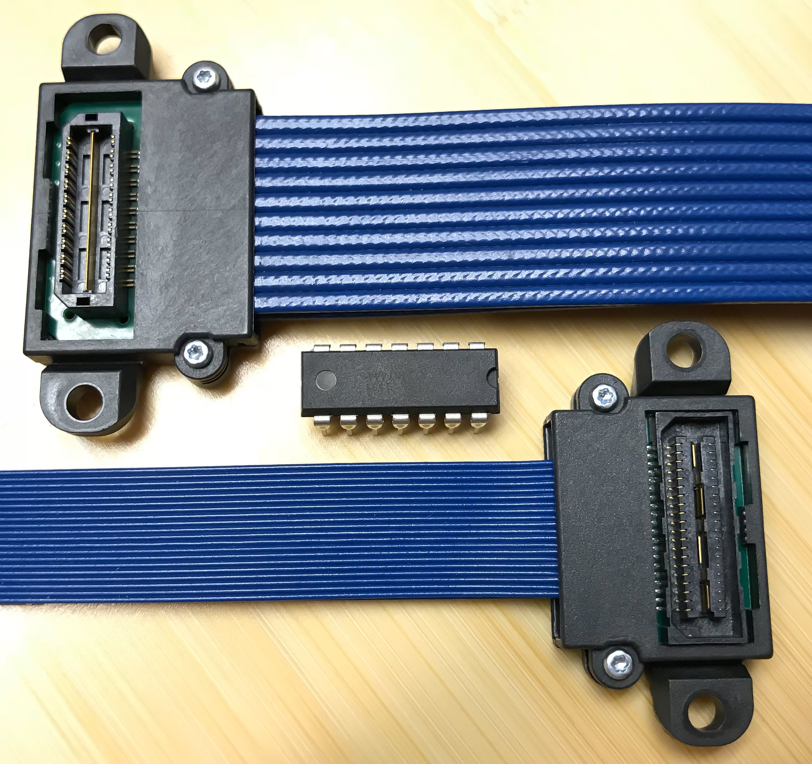
Below are the two cables shown side-by-side with a 14-pin DIP package for comparison. The standard cable on the bottom has a coaxial cable for each of the connector pins. If you’re counting, note that there’s a second ribbon behind this one for the other side of the connector. The transceiver cable on the top has twin-axial cable for each pair of connector pins. Again, there is a second ribbon behind this one for a total of 20 twin-axial cables to carry the 40 conductors in differential impedance controlled bliss.
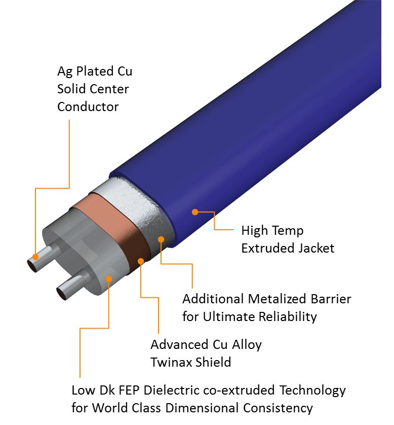
What’s a twin-axial cable? Here’s a nice photo from Samtec to illustrate how each of these is constructed.
In the next update, we’ll discuss the ideas behind SYZYGY DNA.
You can download the full specification and read more about SYZYGY on SYZYGYfpga.io.