Hi!
Sorry for having taken a month since the last update, but in the meantime I have prototyped a new, improved version of STEP400. It is based on the results of the beta testing, with some changes, and I believe this will be the last version of the prototype.
In this update, I would like to inform you about the changes, especially those made to the input and output connectors.
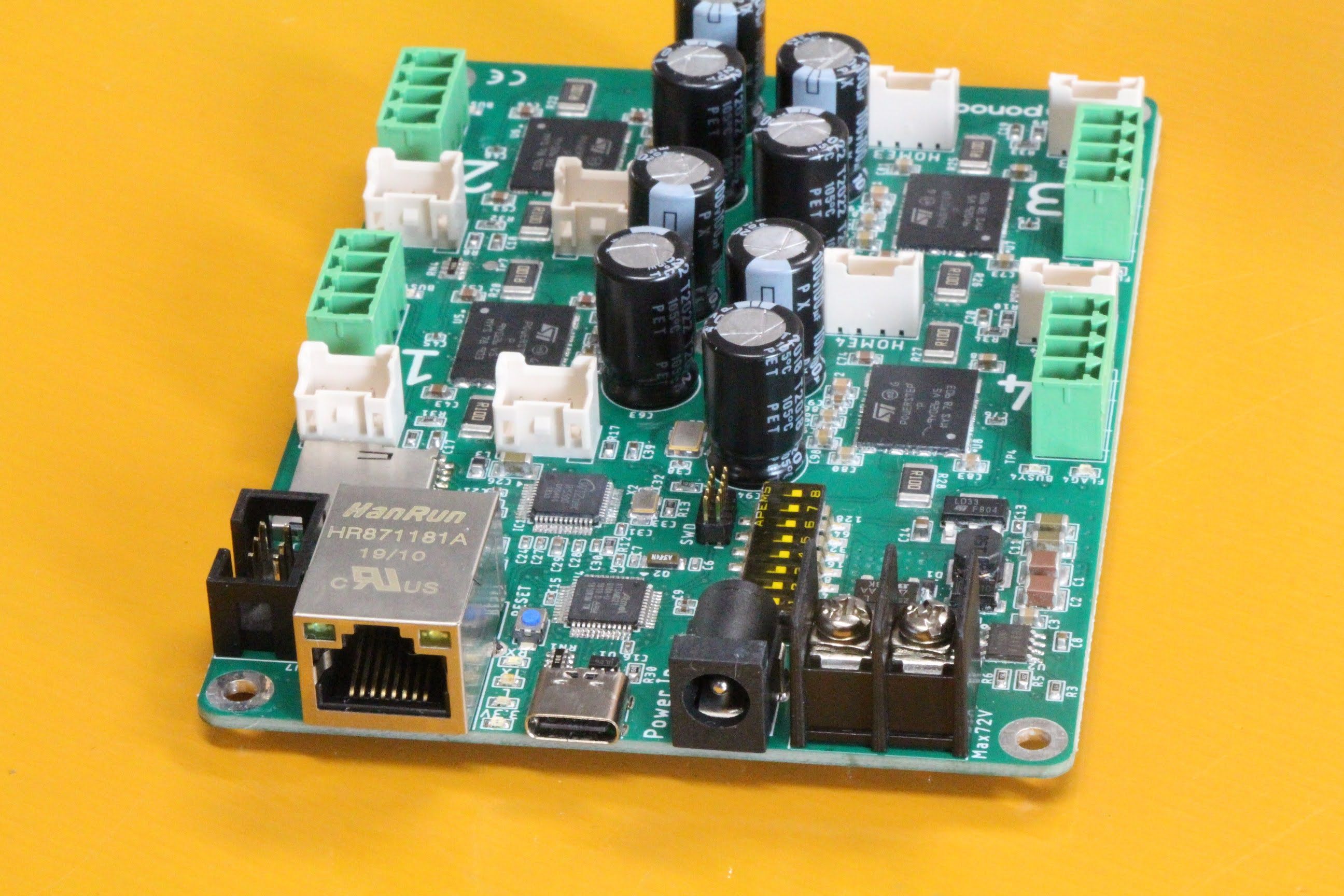
USB
The USB micro B connector has been replaced by a USB Type C connector. When I designed the first prototype in 2016, micro B was the easiest USB port to find, but Type C is gradually becoming more and more available everywhere. In a few more years, USB Type C will be more readily available than other ports, so I decided to change it. This connector can be plugged in either way, up or down, and I think it will be very useful in the field.
Note:
The physical connector is of Type C, but the communication protocol is USB 2.0, which does not support USB Power Delivery. In other words, when power is supplied from a USB power adapter that supports Power Delivery, only 5V/3.3V is supplied to the logic circuits, and a motor power supply is still required.
Power inputs
The previous prototype power supply terminals were a four-terminal screw-type terminal block with two positive and two negative terminals each. This was to provide more room for the large currents that drive large motors, but when I measured the current, I found that one positive and one negative terminal each was more than enough room to handle the large currents.
So I changed the screw-type terminals to two terminals, and installed a DC jack in the empty space. This was to allow you to do a simple test with your AC adapter, as installing cables to the screw-type terminals and arranging a switching power supply were sometimes the first obstacles during beta testing. However, due to the rating of the DC jack, the upper limit of the power supply capacity is 30V DC/1A.
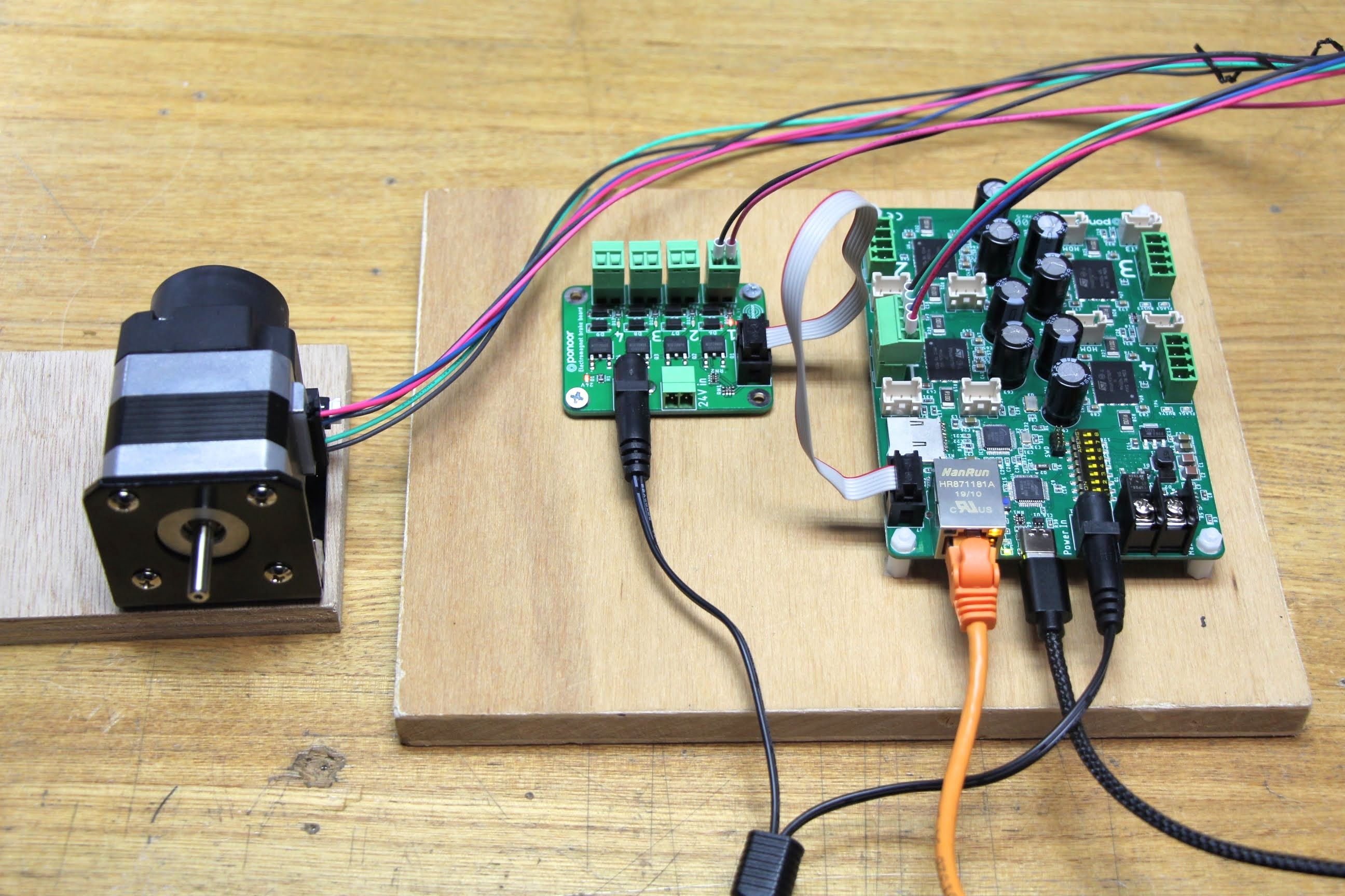
Electromagnetic brake board connector
This is a 6-pin IDC box header for connecting the optional electromagnetic brake board, which outputs a signal to turn on or off the electromagnetic brakes for four axes, but can also be used for other purposes by rewriting the firmware. In terms of Arduino pin names, D1, D5, D8, A1, 3.3V, and GND are connected to each terminal.
I2C pad
The unused I2C terminals and D38 pin pads are exposed on the soldering side of the board. You can solder surface-mounted pin sockets, such as this one for example, which can be used with Arduino Wire library.
LIMIT sensor inputs
In past prototypes, LIMIT sensor inputs were connected directly to the MCU, but this was changed to connect to the ADC input of each PowerSTEP01 with the addition of a pull-up resistor. Although the ADC input is originally intended to allow the PowerSTEP01 to detect supply voltage fluctuations, the new prototype uses it as a LIMIT sensor input by monitoring the voltage on the ADC pin. This saves pins in the MCU and I2C pins are now available for expansion.
Next steps
I’ll proceed with the functional validation of this prototype, but it seems to present no problems. Once the design is finalized, I plan to place a final production order within the next two weeks!
Also, the firmware development continues. The new repository is here, but it is still in preparation stage. I’ll let you know when it is ready to be promoted with finalized hardware design files.