Thank you for joining us for our recent AMA session! Also, thank you to everyone who came to our open studio in Tokyo! Both were a great time and I heard many great ideas.
A clip before cleaning up the open studio the next morning.
Voltage and Current Drive Modes, and Microstepping
The topic of this update is the STEP400 - or rather PowerSTEP01 - motor driver features of Drive Mode and Microstepping. These are important when using a stepper motor, regardless of driver.
Constant Voltage Drive and Constant Current Drive
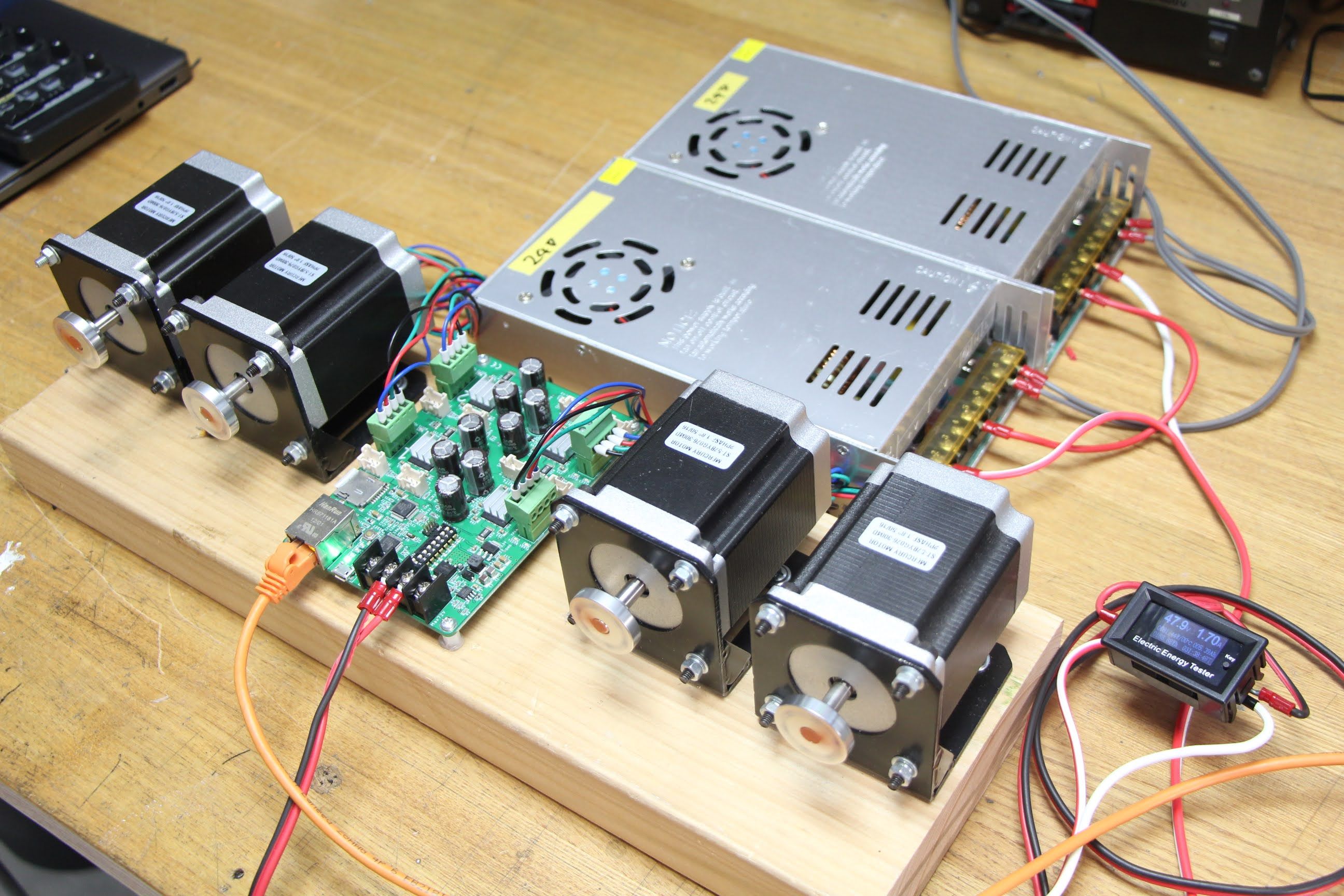
This video shows:
- The difference between constant voltage control and constant current control
- The difference between full-step and micro-stepping drive
First, the motor is run under constant voltage control (hereinafter referred to as “voltage mode”). After around 800 step/sec, the motor cannot run properly and starts to vibrate, then it stalls at about 1,400 step/sec and stops completely. The motor runs quietly until the vibration starts, but in this video, a microphone is attached to the motor so that we can capture the smallest noise.
Next, the motor is switched to constant current control (hereinafter referred to as "current mode"). It is noisy, but it can rotate up to high speed. In this setting, we were able to achieve more than 11,000 steps/sec.
The differences between these two modes can be summarized as follows:
- Voltage mode turns quietly and smoothly, but only works at low speeds.
- Current mode is noisy, but can rotate to high speeds.
The next step is to switch back to voltage mode and then run the motor while switching microstepping modes.
Microstepping
In a stepper motor, one revolution is divided into a number of steps, such as 200 or 400, and there is no in-between steps. Microstepping is a technology that allows you to split the steps into even smaller steps allowing fore increased precision and a smoother movement. As you can see in the demo video, the smaller the division of steps, the quieter the motor becomes.
Positioning In Microstepping
If a motor has 200 steps per revolution, a full step (no division) will have 200 steps per revolution, but a half step will divide a step into two steps, resulting in 400 steps per revolution. In the voltage mode of STEP400, the steps can be divided into a maximum of 128 divisions, in which case the number of steps will be 200 x 128 = 25,600 steps per revolution.
Most of the projects I’ve worked on have fixed the microstepping mode at 1/128. However, in current mode, the microstepping is limited to 1/16.
The Relationship Between Power Supply and Stepper Motor Ratings
Inductance
The windings inside a stepper motor behave like an inductor. When a voltage is applied to the inductance, current does not start to flow immediately, but rises over time. In the case of a stepper motor that repeats the ON/OFF cycle at each step, the ON time becomes shorter and less current flows as the rotation speed rises. Since the torque of a stepper motor is nearly proportional to the current, the maximum torque decreases as the motor rotates at higher speed.
Voltage of the power supply
To overcome this inductance and drive current into the motor, you need to use a power supply with as high a voltage as possible. If you look at the motor’s datasheet, you might see a very low number for the voltage rating, but when you do rotate the motor, it will not be able to deliver the required current at that voltage. In fact, you will need many times that voltage. The actual voltage required will vary greatly depending on the motor’s rating, the speed required, and the load, but in my experience, I see the required voltage roughly as follows:
- Until NEMA17 size : 24 V
- NEMA23 or bigger : 48 V or 72 V for high speed
However, some motors can produce high torque even with a small size, while others can’t apply much current even with a large size, so it’s important to check the ratings.
Current Capacity
The current the power supply can provide is another important factor. A large current may flow at the moment of stalling, and if there is not enough current capacity, protection may be activated on the power supply side, causing the power supply to shut down.
Setting in STEP400
Voltage mode setting
In the voltage mode of STEP400, registers called KVAL are used to specify what percentage of the power supply voltage should be applied to the motor. Also, if a higher voltage power supply is applied, more current may flow than necessary when the motor is spinning at low speed. To adjust for this current imbalance, a group of registers is used to compensate for relatively lower applied voltage at low speeds and higher applied voltage at higher speeds. The calculation of these register values is described in the STMicroelectronics application note.
We have calculated the register values for some motors based on our actual measurements which are available in the form of configuration files we’ve placed in our repo. We have only a small number of these motors at the moment, but we hope to add more of them gradually.
Current mode setting
In current mode, the TVAL registers are used to set the target current value, which can be set up to 5 A in increments of 78 mA in the STEP400. You still need a high voltage power supply to deliver the target current when you’re spinning at high speed. Although the PowerSTEP01’s original capability is controllable up to 10 A, the STEP400 has an upper limit of 5 A due to the power rating limitation of the current sensing resistor. At 5 A of phase current, the torque is quite strong, and the tiniest mistake can lead to great danger. In these situations it is better to use industrial drivers.
Next Update
For the next update, I’ll introduce the simplest way to try PowerSTEP01 chip with the STMicroelectronics expansion board and the Ponoor PowerSTEP01 Library.