Project update 2 of 21
Protection Features
Hiya!
I’ve been claiming that a μArt is robust and that has great protection features. But what does this mean in practice? What can you do, and what shouldn’t you? Can you accidentally kill a μArt and how? Which devices benefit from the protection?
The USB side
Let me start by saying it is not expected that you attach the USB side of the μArt to anything else other than a proper USB host (PC, laptop, SBC, smartphone). Your custom circuit is supposed to be on the "other end" of the adapter, where the 10-pin header is found. USB ports are known to behave well as history can testify, after all you’ve never seen or heard of a computer that supplied reverse polarity or 12 V over its USB port, right? Slightly higher voltages than 5 V can happen, up to at most 5.25 V, but this is covered in the μArt, with an ample 250 mV headroom over what the USB2.0 spec allows. Due to the mechanical construction of USB connectors, it is also impossible to plug in a cable in reverse. My point is, unless you deliberately construct a malicious USB host, there can be no "user accidents" on the USB side, by design.
This does not mean though that USB receptacles are completely worry-free. ESD for example, at least, needs some attention. This is not the place to teach about ESD protection, but suffice to say there are international standards describing the various levels of ESD immunity, and unified and repeatable ways to quantify them. The most relevant and important one, and also the one required for CE marking by the way, is the IEC 61000-4-2 that defines four levels of immunity. The highest level, level 4, requires withstanding ±8 kV and ±15 kV ESD events depending on the method of measurement. The μArt has a USB protection component rated for ±20 kV and ±30 kV respectively.
Now, most devices would stop here (but actually, as the sorry state of current UART adapters goes, most don’t even implement ESD protection). However, there can be one more phenomenon on USB cables that can potentially damage devices. Due to the parasitic inductance of cables and inrush current in the moment of insertion, especially with long cables, when you plug in a cable that is already attached to the computer, the power rail’s voltage (VBUS) experienced at the peer device can overshoot the actual supply voltage of the cable, followed by unwanted ringing. The magnitude of this overshoot is a lot less than ESD, but can still reach multiple volts above the absolute maximum rating of silicon devices and it also lasts longer, damaging them. The μArt has inrush current limiting to limit the resulting overshoot, and its delay-start circuit makes sure operation only starts once the ringing has passed and the bus voltage has stabilized.
The UART side
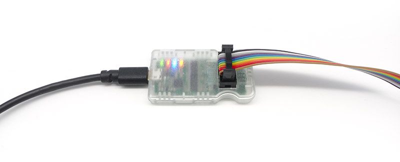
Now, let’s turn our attention to the 10-pin receptacle. Here, the user can connect each pin separately and independently, so there is no mechanical way to prevent false connections like with USB. Granted, the header utilizes a standard polarized IDC header, so you can use a 10-pin connector to connect everything comfortably and guaranteed without error, but you don’t have to. Besides, the UART pinout in application circuits is different for each product anyway, so you could still make mistakes on the other end of the cable. No matter how we look at it, there are just simply more possibilities for errors on this receptacle than on the USB side. Let’s see how we handle those.
First of all, there is of course the mandatory ESD protection here too, with a protection component rating of ±20 kV. There is also reverse polarity protection, which means should you happen to mix up the GND and VIN leads, there will be no damage. You just have to switch them back so they are correct again and it’ll be as if nothing happened. Then there is over-current protection on all IO pins. This means, again, that nothing can go wrong no matter in what false position you connect the pins by accident. Take any output pin (for inputs it wouldn’t matter anyway), short them to GND, short them to supply voltage (VIN), create a driver conflict by hooking it up to another output pin instead of an input, it’s just fine. Normally, any one of these conditions would damage or kill a device, but with the μArt you can rest easy.
Are we through yet? What happens if there’s an IO overvoltage condition, but still within device spec? This can happen for example when you connect VIN to a 3.3 V supply, but connect an input pin to a foreign device that has 5 V output. Well it is certainly a rude thing to do, but the μArt will withstand that too, so no problem here either.
How to kill a μArt
Is that even possible (without resorting to a hammer)? Well, it turns out there is one sure electrical way: Go out of spec with the voltages. I’m not talking about transients like ESD (that’s fine, remember?), I mean hooking up the μArt to stable voltages like +12 V. Don’t do that. As you probably know, this device is rated for up to 5.4 volts. Then there’s a tiny bit of headroom that’s still okay, but it’s only meant to accommodate unclean supplies and voltage ripples. Then when you get to 5.5 V, you are on your own. At this voltage, the ESD protection diodes start to turn on for real, and while it’s not like they’re 100% fully on at 5.5 V, their turn-on curve’s kind of a gamble. Once you burn them down, you might already have a short, and if not, anything above +6 V will damage the ICs in the μArt (though the galvanic isolation will prevent voltages up to several hundred volts from reaching your computer).
Same case of unsupported voltage levels but less obvious, is applying negative voltages to data lines. For example, if input polarity is reversed while the data lines are already connected, data line voltage can show up as negative from the point of view of the μArt. This is easily avoided though by connecting power first. With the μArt, you’ll notice that the power connection is not correct by the power LED not coming on, so this situation is easy to recognize early and you can correct it before you attach any other signal. At this point no damage has been done yet due to the reverse polarity protection on the power line.
So, it can be killed out-of-spec voltages. How likely will this happen? There aren’t really accessible MPUs or MCUs that operate with a voltage higher than 5 V, and while the boards themselves might have higher voltages (say 12 V for motors or input supply), these voltages are always positioned wisely far away from your GPIO supplies or serial headers. Mixing those up is not a mistake you are likely to make. In the end, there is of course always a way to kill an electronic circuit. But given all the things above, I think it is unlikely you will damage a μArt by accident. Just connect your power first (this is good advice anyway for any other circuit too when connecting external boards that are already powered), and then check the μArt’s power LED before continuing.
The cherry on the cake
One last thing that I didn’t point out anywhere earlier. The protections of the μArt have been designed so that they protect not only the adapter, but your own circuits too. The current limiting on the IOs for example has been chosen not to supply the relatively high currents that the μArt itself could handle, but rather the limit in use is low enough so that your Raspberry (for example) also survives unscathed despite its GPIO’s low current capacity. The ESD diodes and reverse polarity detection have been designed carefully to be effective yet not to cause shorts as seen by the peer’s power supply or GPIO.
There’s also the galvanic isolation as a protection feature. For now I’ll just mention that it fully and reliably protects your USB host from basically any fault or mistake that might happen on the UART side. The same isolation even makes it safer for your expensive lab equipment (such as your scope while you are probing your electronics), even if you’re not working with any high voltages. I’ll also show you why, but since there’s a lot to discuss about the galvanic isolation anyway, this is a topic for another update.