Last week, we talked about the design process and revisions of Tigard. This week, we’ll share details about manufacturing - including design decisions, processes, and pitfalls. We’ll finish up with a quick How-To on dumping spi flash.
DFM
DFM stands for Design For Manufacturing. Any design process involves weighing and balancing many different factors - and the manufacturability needs to be balanced against the usability factors we discussed previously, as well as the flexibility of the design, its cost, and its durability.
We tried to keep the design simple to reduce cost of assembly and minimizing manufacturing failures:
- We chose a 4-layer board, allowing a smaller final design without significant risk
- Keeping all the components on one side cuts several steps out of the process
- We could have used all SMT components, but prioritized durability over cost by using through-hole headers
- We used array resistors when possible to reduce part count
- We chose 0402 passive components which are small but still reliably placed on most automated assembly processes and hand-reworkable
Assembly Methods
Through our prototype revisions, we ended up assembling boards using 3 different methods:
Hand assembly
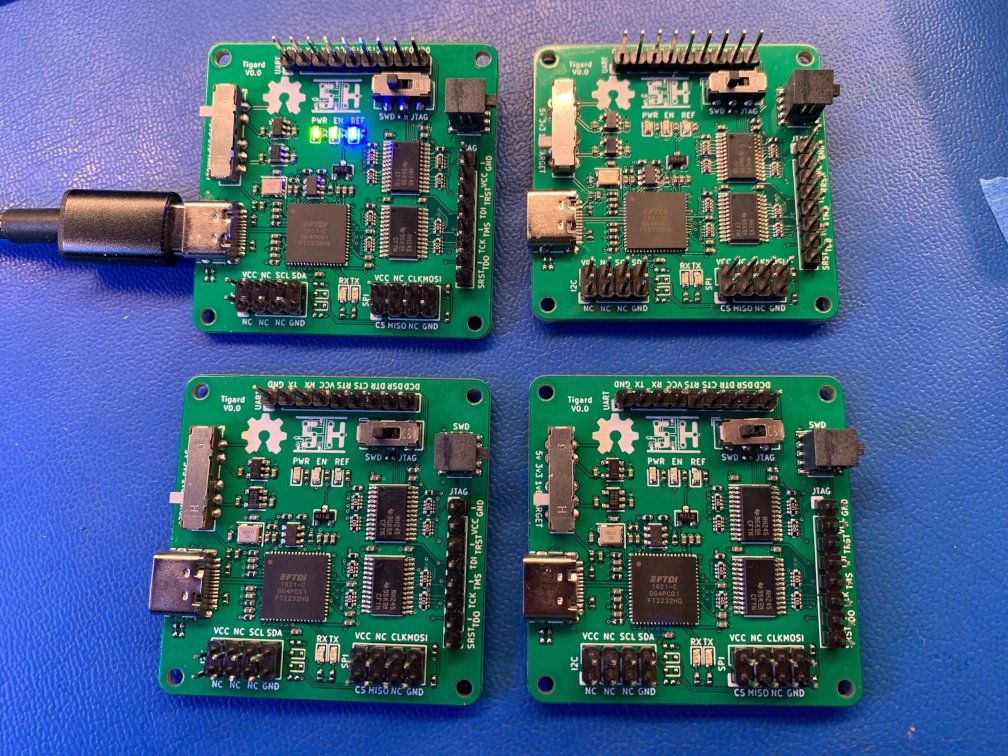
Tigard V0.0 was hand-assembled. @esden manually placed all the surface mount components on one panel of 4 boards using an Interactive HTML BOM plugin for KiCad that shows onscreen where to manually place components. Once the surface mount components were placed, the boards went in the reflow oven, and then the through hole components were manually soldered.
Hand placement would have probably been easier with larger 0603 or 0804 components on a bigger PCB - but our design objective from the beginning was automated assembly.
Small Volume
Tigard V0.1 used a hybrid small volume process. It was worth the time investment for @esden to set up the pick and place machine for the surface mount components since we assembled 80 boards, while @fharding0 hand-soldered most of the through-hole components.
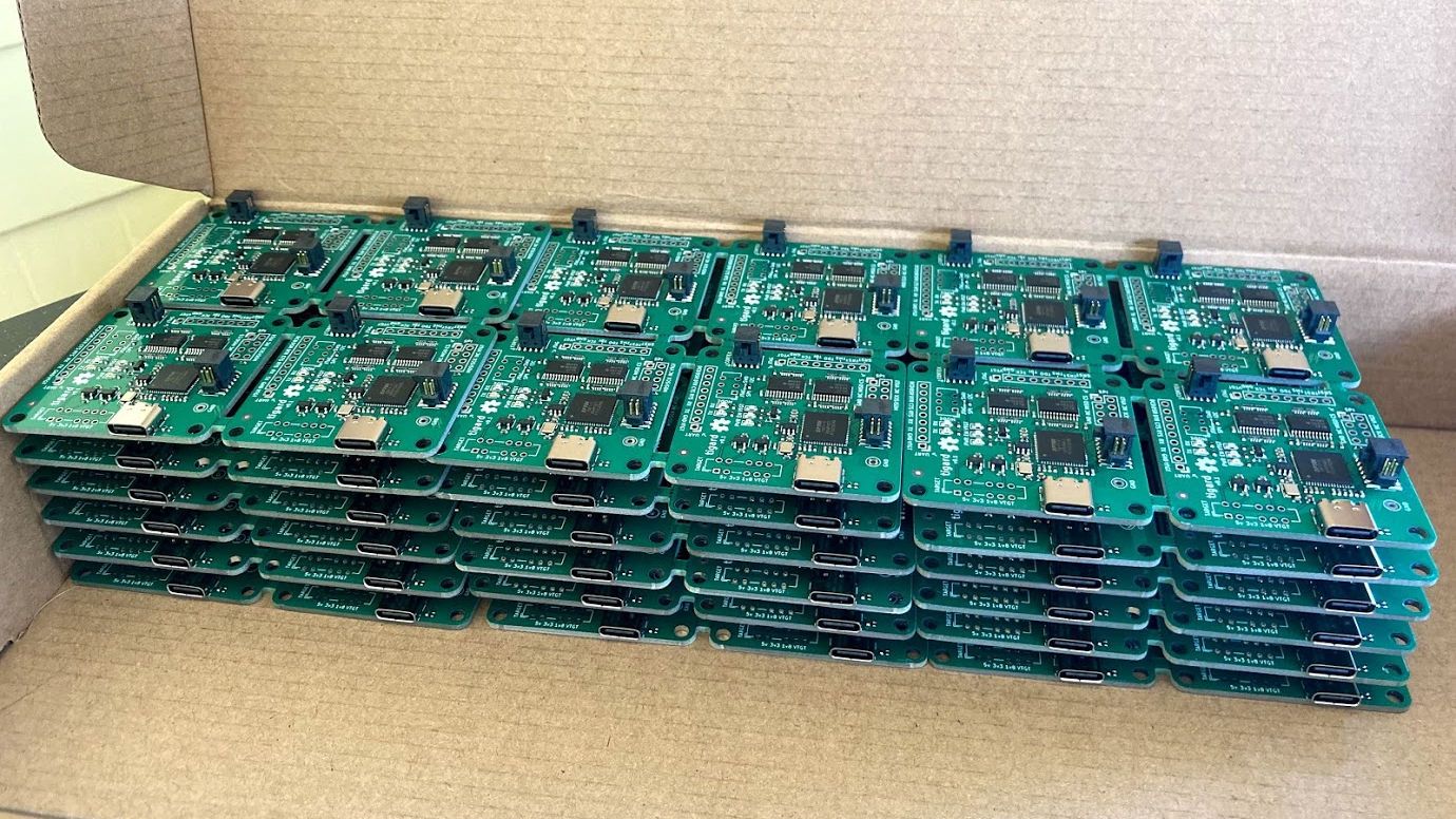
Using surface mount headers would have removed the hand-soldering from the small volume. That might be fine for the prototypes, we’re still sure that through-hole headers were the right choice for durability.
High(ish) volume
Finally, we were ready for production. We were aiming for a production run on the order of a few hundred boards. This is still a ‘small’ job for most manufacturers, but it was huge for us. In addition, this was the first time we’d outsourced both PCB fabrication and assembly together, without much visibility in between. We were wary about potential assembly issues:
- Would our minor changes from V0.1 have averse effects?
- Would the PCBs be manufactured properly?
- Would they acquire all the correct components?
- Would the right components go in the right places?
- Would chips and LEDs be oriented properly?
- Would the overall quality ensure high yield?
Most are fixable issues, but while rework is no big deal for 4 boards, it is a big deal when you’re talking about hundreds of boards. Since it’d almost certainly be manual rework, the rework would quickly cost more than the assembly! However, what if there was a mistake on the PCBs, or major yield issues? The cost of the boards and components might be lost!
To hedge these risks, we considered a prototype run, but the manufacturer quoted over US$800 to run a single panel of 4 boards. If we were considering manufacturing thousands of boards, the cost might be warranted, but it didn’t add up for us:
cost of failure x likelihood of failure << cost of mitigation
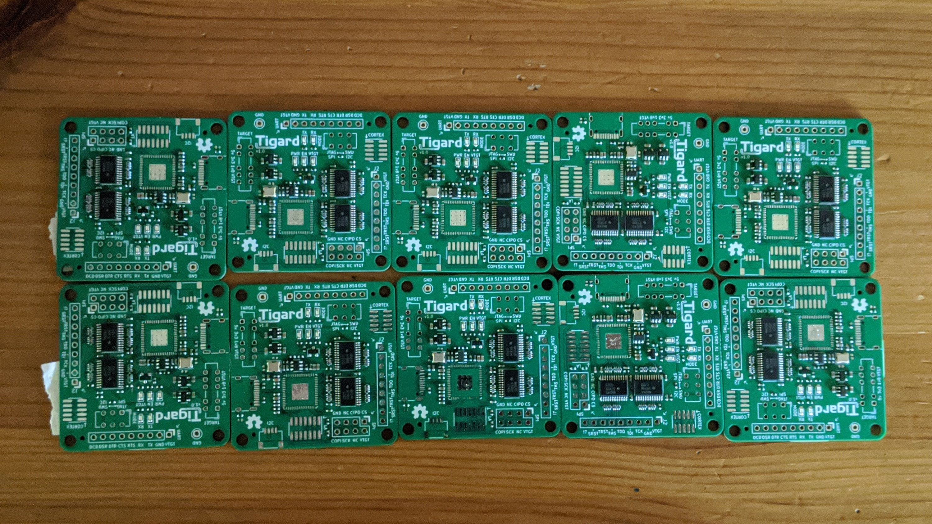
As an alternative, we spent under $100 to have a low-cost PCB+Assembly provider assemble 10 boards. They used our production-ready files, and they assembled only the SMT components they had on hand - resistors, capacitors, LEDs, regulators, and level shifters. In just over a week, we got the boards, hand-soldered the FT2232HQ and headers, and the board tested good! This gave us the confidence to place the production order.
Next week, we’ll share details about how we automated production testing for Tigard. Until then, enjoy this video of using Tigard to dump SPI Flash chips: