Last week, we focused on DFM considerations that went in to Tigard - this week we’ll talk about testing - both the design consideration as well as the testing hardware and software.
DFT
DFT stands for Design For Test. While the linked article focuses on DFT for integrated circuits, the concepts apply to anything you intend to test - which includes anything intend to have working once it’s manufactured.
For our prototypes, we only manufactured a handful of devices. We were reasonably confident in the design and all pins are accessible so there was no reason for testpoints to the board. Sure enough each prototype responded as soon as we plugged in USB.
For production, most of our needs were satisfied by user-facing features:
- Through-hole 2.54mm give easy access to all the external signals
- Status LEDs assist in debugging Tigard itself
Production Testing
When switching to a higher volume manufacturing process, you need to anticipate a few things:
- Not every device will work off the line
- It's not economical to manually test everything at scale
- If a bad device slips through it's going to cost more in time, effort, shipping fees, testing, and satisfaction than it would to test everything in the first place.
To solve this, we built a test jig and software test suite that will be used to test every device off the line.
Test philosophy
Since we had high expectations that most things would ‘just work’ we focused on coarse functional tests. If a board could loopback UART traffic as well as read and write a SPI flash chip, we could expect that the FT2232H, level shifters, and voltage regulators were probably all working just fine. Rather than have an active test device, we chose to make Tigard test itself while hooked up to a test target. Before starting on the hardware, we prototyped scripts for each of the following test cases
USB
Can we connect to the FTDI device?
This tests the socket, FT2232H, and oscillator. We implemented this with a shell script to detect whether a Tigard board was attached based on the length of the response to:
lsusb -d 0403:6010 -v 2>&1 | grep iSerial | awk '{print $2}'
UART
Can we loopback 115200 bps serial commmunication?
This tests the level shifters, VTGT selection, and UART headers. We implemented this based on a shell script kindly posted on stackexchange
GPIO
Can we loopback additional I/O pins?
By independently setting each output pin high and low, we can only be sure that they are properly connected (no open circuits). By also setting all other output pins to the OPPOSITE value, we can also be sure that there are no shorts between different I/O pins.
We implemented this with a python script using PyFtdi’s GpioAsyncController API
SPI
Can we read a SPI Flash?
This is one of the most common uses for Tigard - it tests several pins concurrently, along with level shifting and high speed data transfers. We implemented this with a python script that uses PySpiFlash to dump the contents of a spi flash chip
VCC
Are the on-board voltage regulators working properly?
There’s no built-in way to check this. If our 3.3v regulator and 1.8v regulator were swapped, they would still work fine in loopback mode. To test this, we put an MCP3002 SPI A/D Converter on to our test jig, which we use Tigard to speak to! A few lines of PyFtdi are enough to send a request to the A/D converter and convert the return data as a voltage:
...
v1=adc.exchange([0x18], 1)[0]/255*5
v2=adc.exchange([0x1c], 1)[0]/255*5

if v1>1.6 and v1<2 and v2>3 and v2<3.6:
    exit(0)
...
EEPROM
Can we flash/read the EEPROM with a serial number?
ftdi_eeprom comes with the libftdi1 library, and has all the features needed to read and write the EEPROM. A shell script interprets the response to make sure it is successful
Hardware Test Jig
Once we knew what our test process would look like, we needed a test jig.
PCB
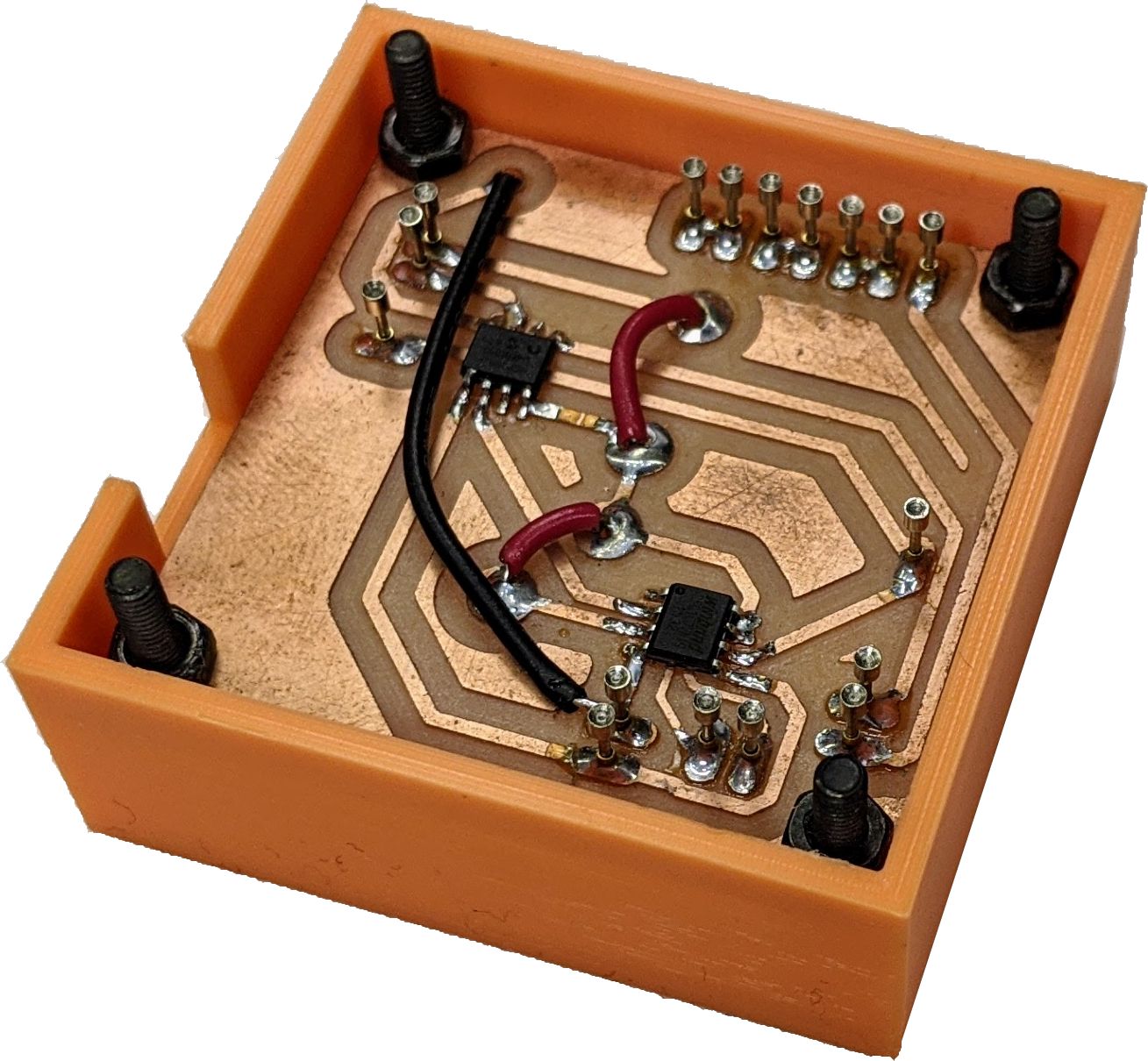
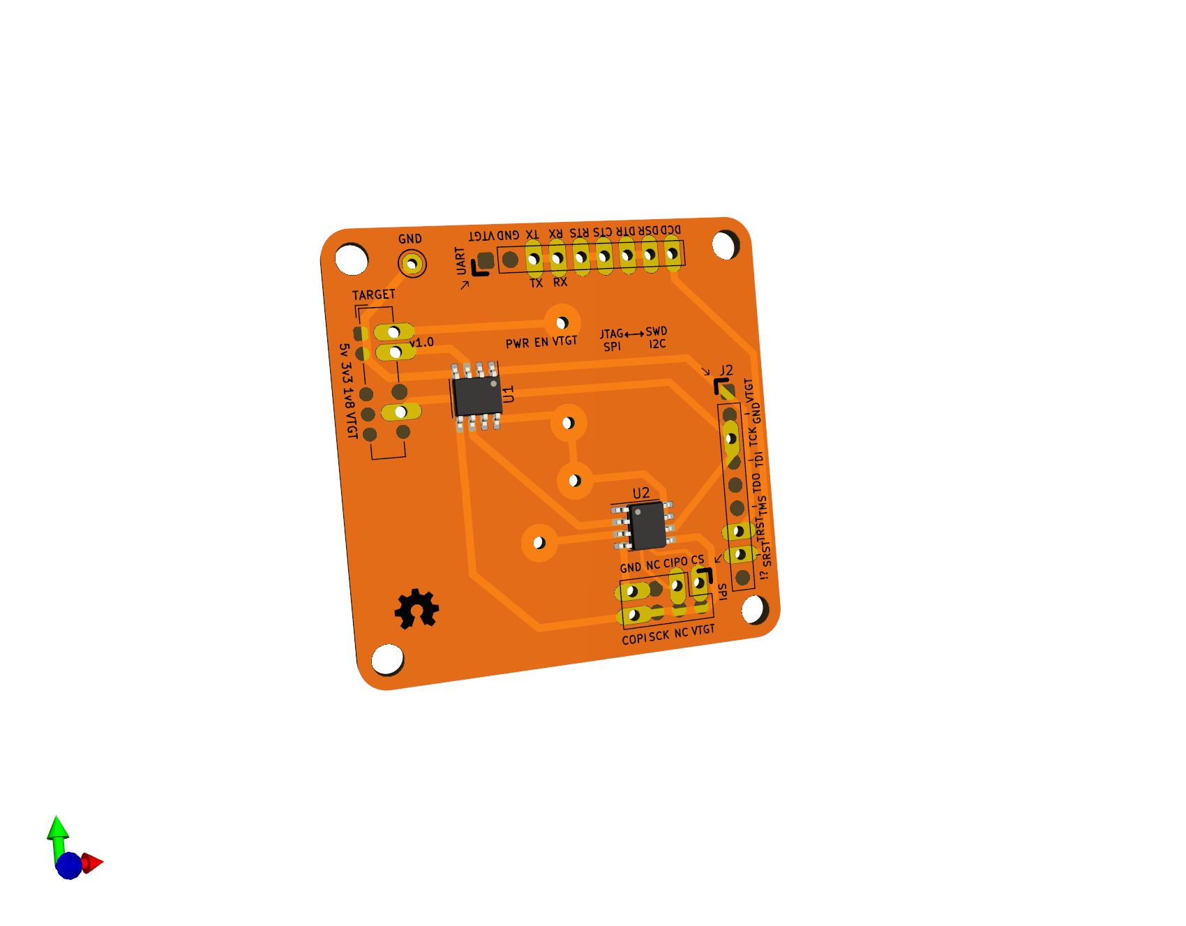
Spring loaded pins with a ‘cup’ tip (P75-A2) would let us connect to the bottom of the through-hole pins, but we needed them to be in just the right spots. We took the Tigard PCB layout in KiCad, and removed all the components except the through-hole headers. Then, we added on our test features:
- loopback wire from UART TX to RX
- loopback wires for all the GPIO pins
- SPI flash chip to be read by Tigard
- SPI ADC, with a different select signal from the flash chip, to monitor the 3.3 and 1.8v supplies
Since we only needed one (and it was already last minute) we laid out the traces very coarsely and made the board on a PCB mill:
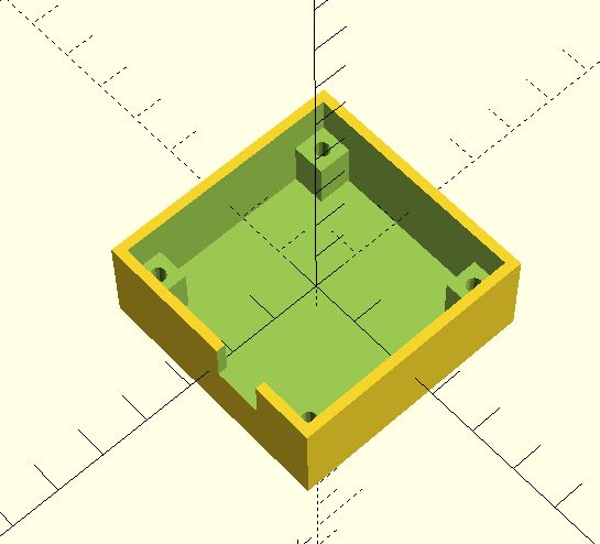
Holder
Next, we need to hold that board in place. Tigard has mounting holes for M3 screws, spaced 40mm apart in the corners. Using OpenSCAD, we modelled the mounting holes in a box large enough to hold the PCB, plus enough space for pogo pins to stick through the board. By specifying lots of slack in the measurements, we were able to get things good enough by our second print.
Bundling it all together
After soldering the components and pogo pins, we only needed standard M3 screws and bolts to hold the jig in place inside the printed box as well as align the Tigard board being tested.
We prototyped all our test cases on a lab computer, but wanted something more portable for the final product. We opted for a Raspberry Pi since we had enough lying around. By adding an OLED display and running the test suite on boot, we made an automatic standalone test controller. Take a look at the video to see how it worked!