Project update 10 of 10
An In-Depth Tour of the Design Files
by Zhuyuan SHello backers,
Thank you for your support. Previously, I have published all the source code and fabrication files on GitHub. Today, I am going a step further and publishing the whole design project, so you can modify the design as you wish.
The design file is hosted at OSHWHUB, an open source hardware hub provided by JLC. JLC also provides free online EDA software called JLCEDA. You can manufacture this board using PCB and SMT services from JLCPCB. You’ll find access to the schematics and PCB design at our OSHWHUB site. {ymfc-drone-schematic-design-english}
The schematic page will open using the online EDA software (which supports various languages). {ymfc-drone-schematic-eda}
The process is similar, if you want to open up the PCB design file. {ymfc-drone-schematic-pcb}
Schematic Details
The video below compares the Mini-Drone schematic with the original YMFC project.
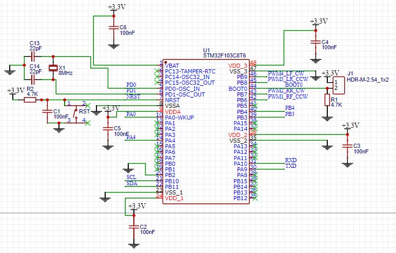
The main controller connects with all other parts on the circuit board. It is powered up by an LDO. It receives attitude information from a MPU6050 over IIC, receives PPM signals from radio receivers throughthe PA0 port, and controls four motors via PWM. Besides that, it uses an analog pin to measure battery voltage, controls LEDs that show status, and connects to a computer through a serial port. The J1 port is for firmware downloading. When you flash the firmware, you’ll need to short circuit J1 with a jumper. But in normal mode, J1 is an open circuit. {ymfc-drone-mpu-6050 | small}
Pictured above is the MPU6050. It connects to the STM32 over IIC, providing attitude information.
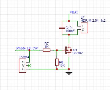
This is one of the circuits that drives the motors. It’s marked PWM4_LF_CW, meaning it controls the fourth motor. It can directly control ESC for a brushless motor, or it can be used to control a MOSFET as shown above. The LF port is a two-pin port for connecting to a brushed motor.
In order to control two types of motors, you need to modify the code a bit, which as explained here:
If you want to control a brushless motor, this video will be helpful:
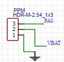
This a three-pin port that receives PPM signals from radio receivers. You can also design your own receiver using Software Defined Radio, which is explained in these three videos:
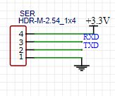
This is the four-pin port used to flash the firmware from a computer to the STM32. It can also be used to retrieve information when debugging.
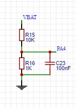
This is a voltage dividing circuit, which provides a value proportional to the battery voltage. This can be obtained through analog pin of STM32 to determine the state of battery.
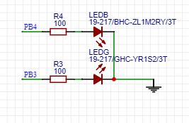
There are two LEDs, controlled via two pins of the STM32. They’re convenient as a status indicator while the drone is flying. {ymfc-drone-bottom-schematic}
This is the last part of the schematic but it is important.
From left to right are the battery connector, power switch, LDO (provides 3.3 V to the circuit). When designing the PCB, we took care to make sure power lines were wide enough that the battery can provide enough current to the MOSFETs and motors. If not, the motors won’t be able to lift the drone and the STM32 could even reboot unintentionally.
Other Resources
For help assembling the board yourself, see:
Watch this video for help flashing firmware onto the STM32 using the Arduino IDE:
For help installing a video transmitter and decoding its images using an SDR, watch: