Project update 15 of 19
Scaling Up
Bottlenecks
A pattern has been emerging the last couple of months: just when I think I’m going to finally catch up production to fill all pre-orders, more orders come in and I’m again falling behind. This is of course a good problem to have, but it’s a problem nonetheless and it needs fixing. The first step in this is identifying bottlenecks that prevent me from producing LiFePO4wered/Pi+’s as fast as I should.
The most obvious bottleneck is of course me. :) I’m working toward the eventual goal of being able to outsource the complete manufacturing so I don’t have to touch each and every unit before it’s shipped. Unfortunately, we’re not there yet. The test fixture has quirks that need to be managed and it doesn’t cover all failure modes I’ve encountered yet, so for now, it looks like I’ll have to continue to do testing in-house.
The second bottleneck that has become obvious is the installation of 40-pin headers at Colorado Tech Shop. This seems to be a worse bottleneck than myself at the moment in fact. As I test assembled units and pass them back to Colorado Tech Shop for header installation, it sometimes takes weeks before they finish up a batch. They don’t have the manpower to deal with the manual labor involved at the volumes I now throw at them. It’s the reason why some orders with short non-stackable headers are still not filled—I’m still waiting on units with short headers installed to be returned to me.
Changes to scale
First of all, the way the product flow is right now is kind of stupid. The CM produces panels with SMT parts installed, I remove the boards from the panels, program, test and calibrate them on the test fixture, then pass them back to the CM to have headers installed, then they come back to me and I install battery holders as needed and do final testing before they are shipped to Crowd Supply for distribution. There’s too much back-and-forth logistics in that. To be able to scale this needs to be streamlined.
A problem is that my test fixture is currently only compatible with boards that have no headers installed. Some of the pogo pins connect to pads that are part of the header, which doesn’t work once a header is installed. My initial thinking on that was that I didn’t want to install a costly header on a board that was bad. Turns out not many boards are bad, but the decision to do this was bad in hindsight. :) It relied on the flexibility and convenience of bringing product back and forth from Colorado Tech Shop which is local, but it doesn’t really work if they can’t keep up. It should have been obvious I needed a product flow that didn’t rely on having a local CM, but then again I also hadn’t expected to be over 500% funded. :)
I recently came to the realization I had less than 200 populated boards left in stock, so a decision needed to be made in how to proceed with a new batch in a more scalable manner. At around the same time I was approached by PCBWay with an offer for sponsorship of one of my Crowd Supply projects. So I decided that this would be a good thing to try as I was outgrowing Colorado Tech Shop’s volume capability.
Of course, when dealing with a CM in China, sending the boards back and forth to have the headers installed after programming and testing is not an option. So I made the decision to have them install headers right away as part of the assembly process, and I’ll have to change the fixture to deal with this. To be able to continue to test using pogo pins I added extra test pads to the layout of the PCBs they will be producing.
An order for 1000 more boards is now placed with PCBWay and we’re looking at delivery around mid-May. After that I’ll have removed one bottleneck which will hopefully help me keep up with current demand.
Red light fix
Since I was going to produce new boards, I needed to find a fix for the problem some of the current boards had where the red charging light would come on even if the unit wasn’t charging. It wouldn’t make sense to produce another batch of boards that could have this issue. It took a while to figure out a good solution, but I’m pretty sure I have one now. I reworked 10 boards that had been returned for this reason with my solution and they are all working fine now.
The problem existed in the circuitry I was using to disconnect the charger from the battery when not charging to reduce leakage current. I use three MOSFETs to do this, and in the old circuit they were driven through dual diode D1 from the CN3801’s CHRG and DONE pins:
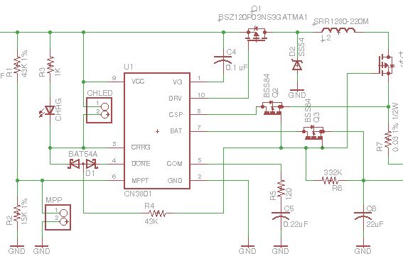
In all the LiFePO4wered/Pi3’s and the early LiFePO4wered/Pi+ batch I made, this always worked as expected. The CN3801 has an under voltage lockout at 3.8 V nominal, 3.1 V minimum, and my assumption and experience up till then was that this would keep the CHRG and DONE pins from turning on when the only voltage powering the CN3801 was battery voltage leaking back to this circuit through the diode drop of Q1’s body diode. The pass transistors would be turned off and the circuit would not leak back to the charge input.
But what I’m learning as I’m scaling to higher volumes is that you always run into new unexpected issues as you scale up. When you make 10 prototypes that work great, you will probably run into some 1 out of 20 problems when you make 100 units next. When you have fixed those problems, your next 1000 unit batch will still have some 1 out of 200 problems. And so on. The upside is that the circuit and your yield improves with every step in this cycle until it is high enough you can live with it. Of course, this also depends on component batches etc., so you might have a 1 out of 100 problem even after you’ve done a batch of 300 previously as was the case here.
In this case it seemed that not all CN3801’s would keep their CHRG pins from turning on in the under voltage condition. To be honest, the spec never said that they would, this had been an assumption on my part confirmed by experimentation on an apparently too small number of components. I have now changed the driving circuit for the MOSFETs to what’s shown below:
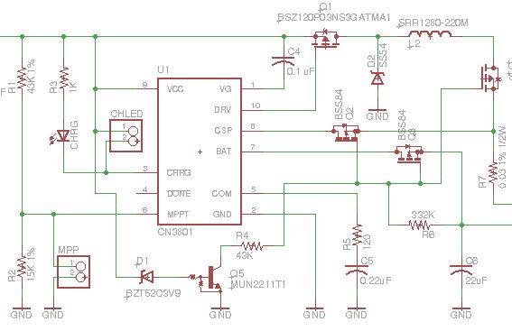
The circuit with zener diode and pre-biased transistor doesn’t depend on variations in the CN3801 anymore. Instead it depends on variations in the zener and transistor thresholds. Which can be just as problematic of course. But I think I’ve calculated the tolerances well enough to be pretty confident it will work as expected. Being based on a current driven device like an NPN transistor with pull-down on the base has the added benefit that it presents a bit more load than the purely MOSFET based circuitry I had before, which could more easily be turned on by small leakage currents.