Project update 16 of 19
PCBWay First Article
I received first article boards from PCBWay, and it’s a mixed bag unfortunately.
Test and programming fixture hack
When I received word PCBWay’s first article boards were on the way, I had to make sure my test fixture was compatible with the new boards with headers already installed. Recall that my test fixture was originally designed for PCBs without headers installed, and expected to be able to make pogo pin connections on pads that are part of the Raspberry Pi GPIO header. The boards from PCBWay will come with headers already installed, so this needed to change, and I added test pads to the layout of the new boards for this purpose.
What a person with extra time on their hands should have done is respin the test fixture PCB with all the pogo pin connections in the right places. What this person without extra time did instead was quickly hack the existing fixture to have pogo pins in the new places and remove the ones that were intended to connect to the GPIO header pads. :)
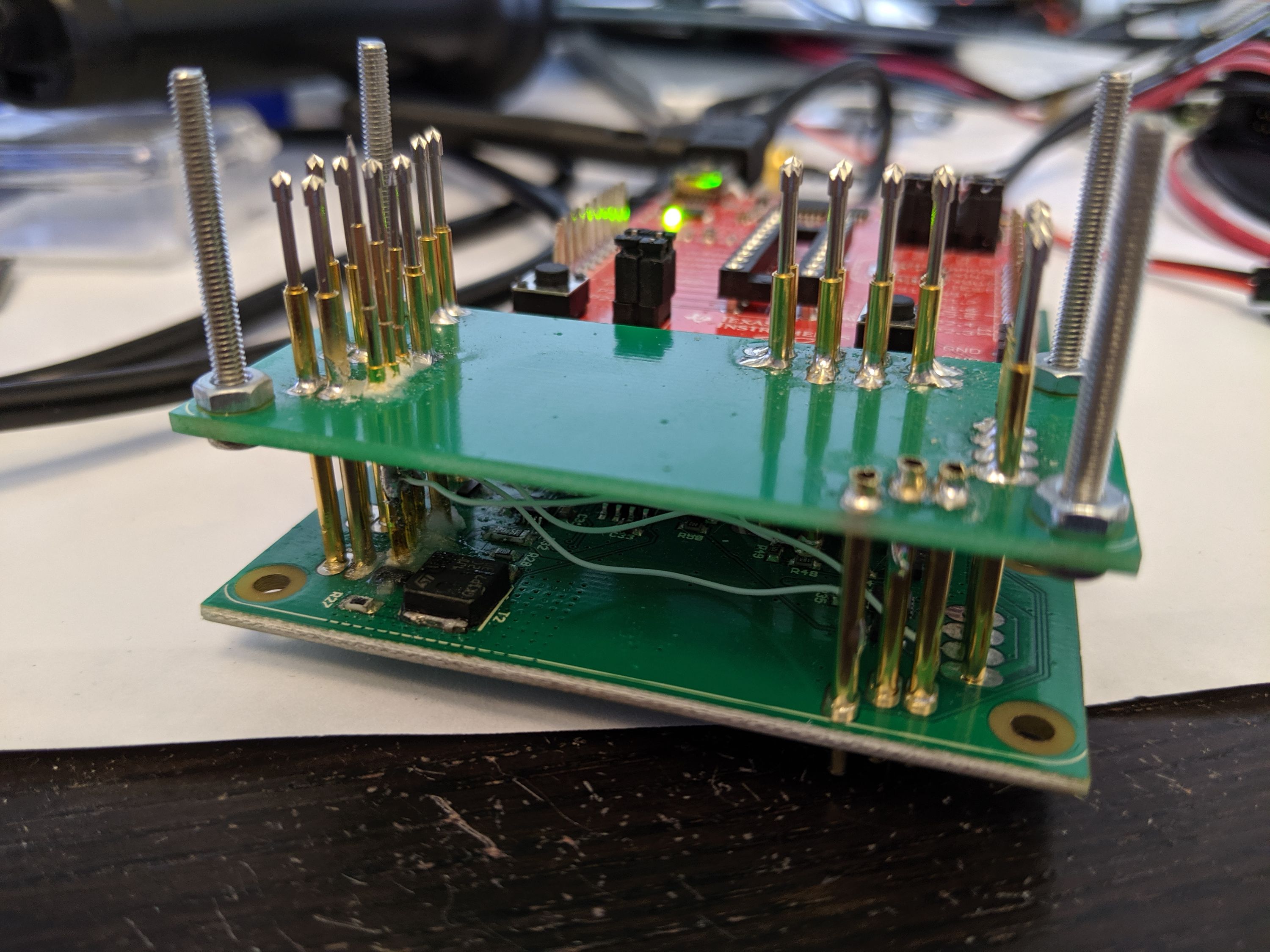
After some sawing, drilling, CA glue with baking soda, and soldering, I now have something that works. I needed to use thinner, shorter pogo pins for these new signals because the pogo pin sleeves were going to sit on top of the bottom board because there is circuitry in the way. These thinner pogo pins have turned out to be quite fragile compared to the larger ones unfortunately, so it was a bit of a battle to get it all to work. It definitely didn’t turn out as beautiful as I had hoped, but it works and that’s what counts at this point.
PCBWay’s sloppy first article
When you start making electronic hardware, you somehow assume that PCB assembly is a "solved problem". You expect that if you farm out your design to a professional manufacturer, they’ll run with it and you will receive beautiful, working boards. It amazes me that after all this time, this still doesn’t seem to be the case. Time and again, PCB assembly houses manage to surprise me with sloppiness and hack jobs, and doing stupid stuff that you really didn’t think you had to mention they should or shouldn’t do.
In my most recent wESP32 update I mentioned how the Mexican CM I’m using for that board swapped two parts of different sizes and somehow didn’t notice it, and also covered the bottom of the board with gobs of solder, closing off pads that needed to stay open. Now it was PCBWay’s turn to disappoint me.
The PCB quality and SMT mechanical assembly are actually alright, I mostly have no issues with those (see below). It’s the manual work that turned out to be really bad. The first thing I noticed was that I could not remove the protective spacers from the stackable header pins. At first I wondered if PCBWay didn’t realize customers need to be able to remove these when they want to install another HAT on top of the LiFePO4wered/Pi+, and they had glued them down. But after prying at them for several minutes, I finally was able to remove them and saw the reason why they didn’t want to come off: the pins were covered with solder all over the place!
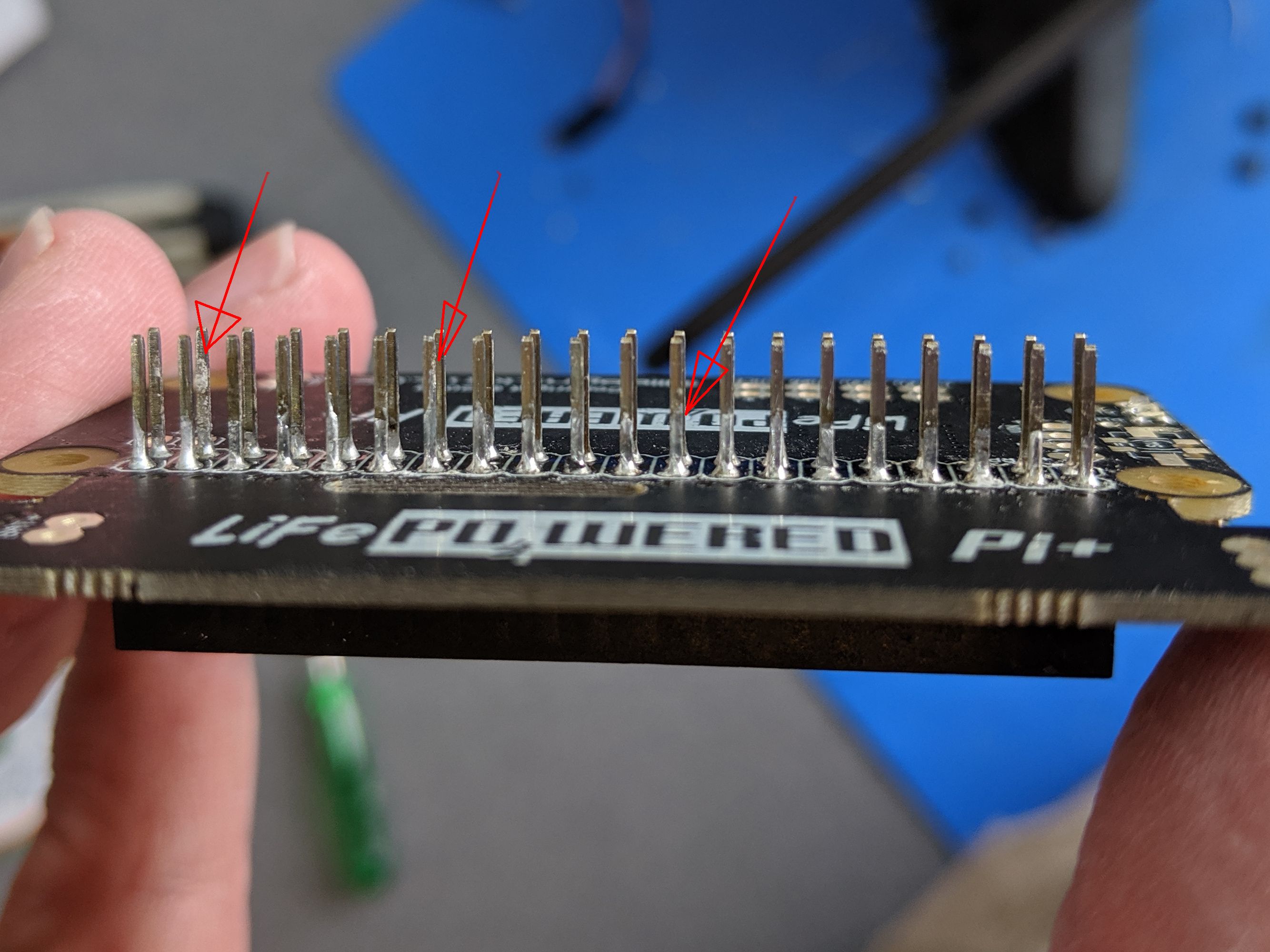
The arrows indicate some of the worst (highest up the pins) cases, but it’s just bad all around. And this wasn’t just one bad sample: all stackable header samples were like this. I had been used to the nice professional job done by Colorado Tech Shop and really did not expect to receive such a mess, especially after I had specifically explained that the pins needed to stay clean. Not only would customers have a hard time getting the spacers off these boards, I doubt that the pins would fit into another header at all, making these boards worthless for stacking.
Next there were the randomly mounted LEDs. I assume that since the back side of the board only has the two LEDs on it, PCBWay must have decided to mount these manually instead of using pick-and-place with reflow. Colorado Tech Shop has been doing the same. But their LEDs haven’t looked like this:
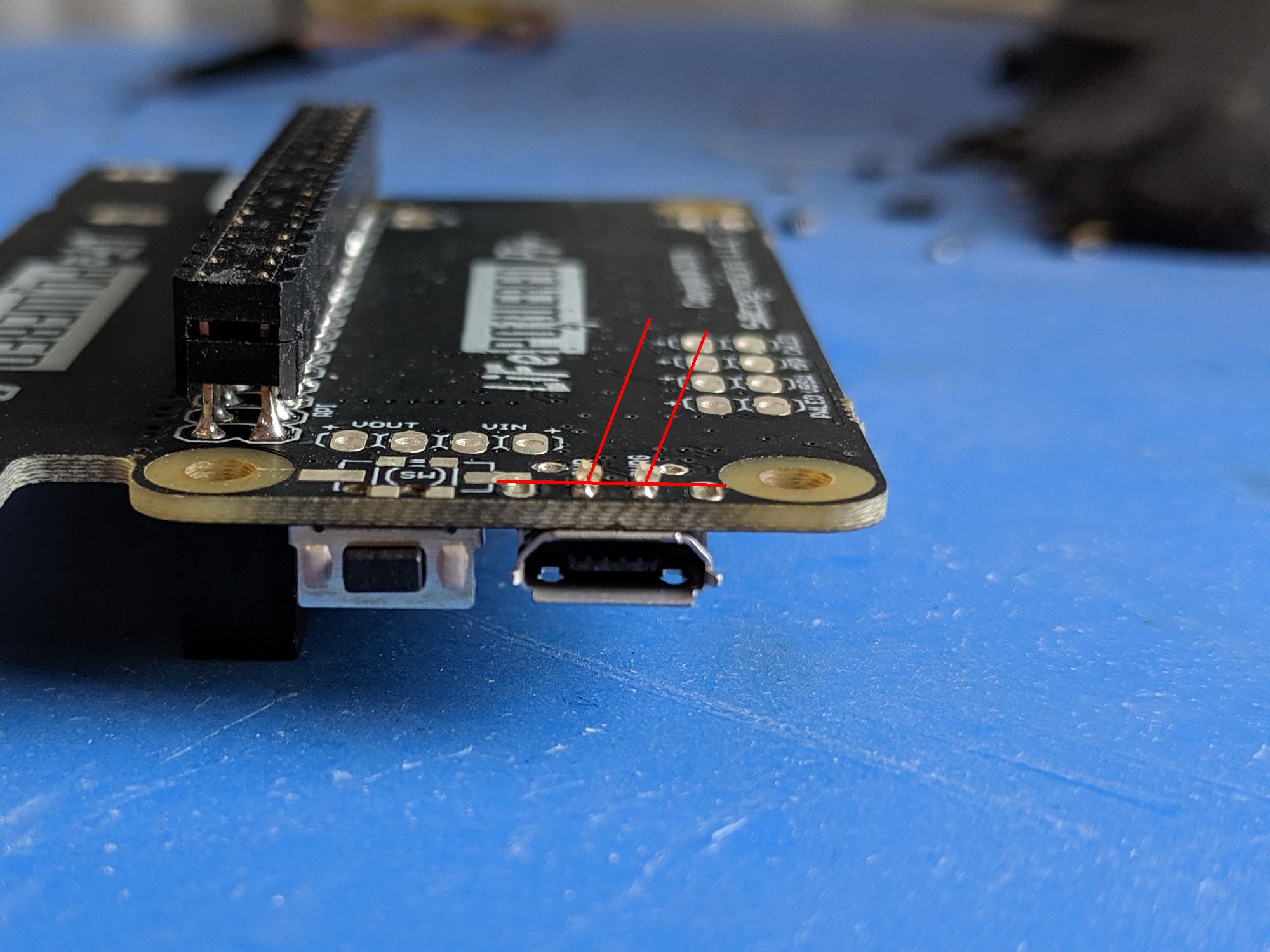
I indicated the "up" direction of the LEDs, the way they were mounted, in red. On other boards, they would lean the other way. On one, they were cross-eyed, with one LED leaning this way and the other one the other way. I just wonder: since when is it necessary to specify to a contract manufacturer that you want your components installed flat onto the board and not at weird angles? Isn’t this supposed to be assumed?
The last problem had to do with the reflow of the SMT parts. On 2 out of the 10 samples, the TPS61236P boost converter needed to be reflowed for the unit to work. On one board, the crystal also needed to be reflowed. Not a great yield percentage, this needs to be better. I don’t want to be reworking 200 out of 1000 boards when I get them!
Next steps
I have communicated all these concerns to PCBWay and requested that they fix these issues and send me another 40 samples (good ones this time!) to increase my confidence. I also suggested they optimize their reflow profile to increase yield on the boost converter. With the large amount of 2 oz copper on these boards, they have a pretty high heat capacity and may need more soak time to get them to temperature equilibrium before starting to reflow.
Moral of the story: never skip first article inspection. You can’t trust that your contract manufacturer will do the right thing until you’ve seen their work. On the downside, they now have to do another sample run instead of moving full steam ahead with production, which will eat up more time before I get new stock. But I’d rather get good quality stock than bad stock. :)