Project update 12 of 17
Manufacturing & Documentation Progress
by Patrick VManufacturing Updates
It’s been almost two weeks since the campaign ended so it’s time for an update on the manufacturing status. First, the HR861153CE RJ45 connectors for the ManT1S-Bridge are on order with Hanrun and they project a ship date of February 2, 2026.
Second, I also received the PMS150G chips that I was going to test for the microcontroller that configures the Ethernet switch instead of the PMS150C’s I’ve been prototyping with. Unfortunately, I can’t seem to get my PMS150G’s to program using the 5S-P003 programmer I have, and the manufacturer provided instructions. The programmer doesn’t seem to detect the presence of the chips. I’ve put the question to Padauk but I’m still waiting for a solution. If this takes too long, I’m just going to go ahead with ordering the PMS150C pre-programmed, which is just a tad more expensive.
Why am I using these oddball OTP micros? Well for one thing they’re dirt cheap, and for simple tasks such as this I’ve found it extremely convenient to buy them pre-programmed and have my CM assemble them to the board just like any other fixed-function part, and not have to worry about programming infrastructure in production. It’s a nice way to lower costs and streamline operations at the same time! I’ve used them in past revisions of the wESP32 and on current production of the RP2040-Shim with great success.
Documentation & Files on ManT1S.net
Some documentation has landed on ManT1S.net! For now, it mostly consists of the same information that was already shared in campaign updates, reformatted to work as guides instead of updates.
A few engineering files have landed as well: the ManT1S rev 5 schematic is now available as promised and I have also a ZIP file with KiCad symbols and footprints in case you want to start developing PCBs that integrate the ManT1S. The grid below shows the four symbols that are available:
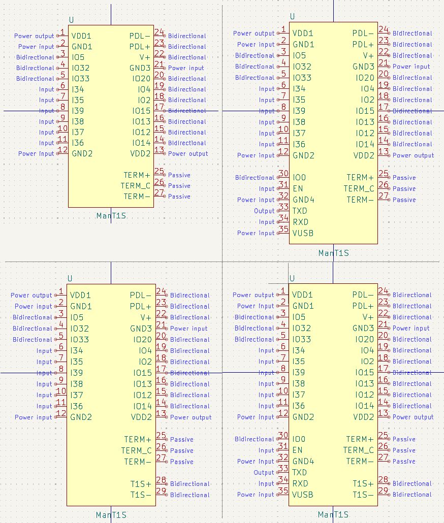
Why four variants? Because of different possible use cases for the ManT1S. For one thing, you can buy the ManT1S with and without the T1S screw terminal installed. If the T1S screw terminal is present, you don’t need to connect these signals to your own PCB, so they are omitted in the symbols on the top row. The latter case where the T1S screw terminal is not installed is useful if you’re integrating the ManT1S and you have your own type of connector you want to use for the T1S network connections. The signals are made available to your PCB and you can connect them to whatever connector you want. For this use case, use the symbols on the bottom row.
In addition, if you decide that you don’t need the programming connections for the ESP32 brought out to your own PCB, the symbols in the left column omit those connections. If you do want them connected to your PCB, use one of the symbols in the right column.
In the footprint library, there are seven footprints total: six SMT variants to surface mount the ManT1S directly to your PCB, and one through-hole version in case you want to use headers.
The SMT variants are similar to those for the symbols, but there are two options in case you’re not connecting the programming header to your PCB: either you have nothing where the programming pads are (for instance, if you intend to use pogo pins to connect to the ManT1S programming header from the top), or you can have a PCB cutout in case either you want to be able to reach the programming pins from both sides of your PCB, or you want to solder in a wESP32-Prog-C, and allow its pins to stick through your carrier PCB. The footprint versions with T1S screw terminal installed feature a similar PCB cut-out around the T1S connections so the module can be installed flush with your carrier PCB despite the screw terminal pins sticking out.
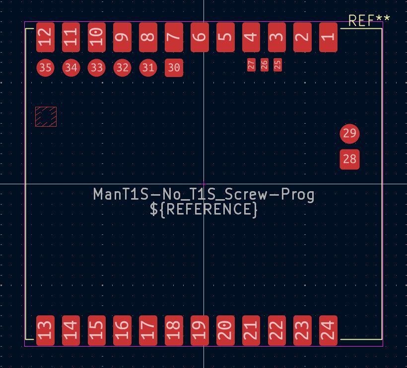
Below is the footprint for the module with no screw terminal installed and all the connections to your PCB:
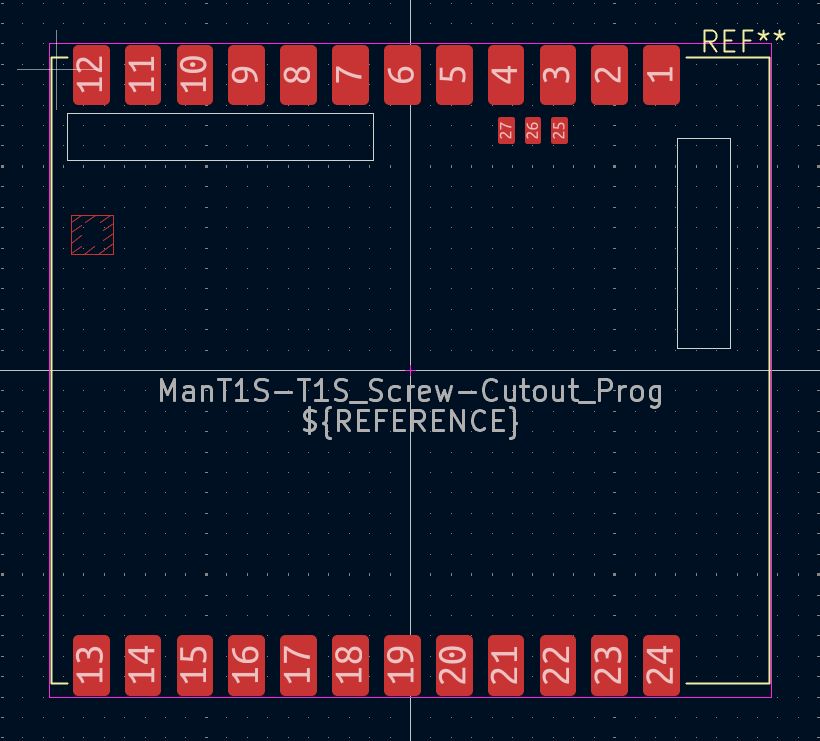
And here is the minimal footprint with cutouts for the case where the screw terminal is installed, and you want access to the programming port from both sides:
All the SMT footprints have connections to bring control of termination to your board, either to bridge by physical jumpers or under electronic control. They also have a keepout area under the U.FL antenna connector.
Let me know if there’s any use case I’ve overlooked that may need a different footprint variant and I can add it to the library!