Project update 3 of 7
Shrinking Power Over Ethernet
by Patrick V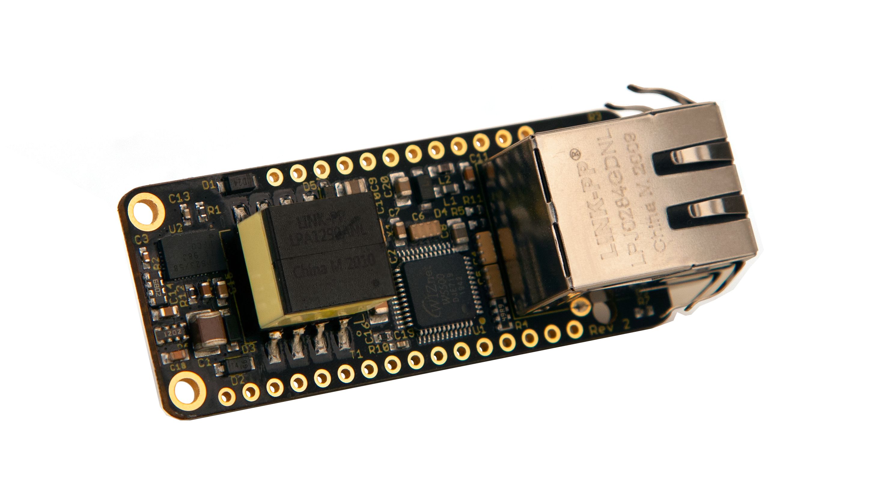
Some of you may know that this is not my first Power over Ethernet (PoE) project. At the end of 2018, I ran a Crowd Supply campaign for the wESP32, an ESP32 board with 90+ Mbps of Ethernet bandwidth and 13W of PoE power. It was around this time that someone asked if I could make a PoE FeatherWing.
The challenge
At the time I wasn’t sure this was feasible at all. The PCB area used for PoE on the wESP32 was roughly 1430 mm2, while the total PCB area available on the Adafruit Ethernet FeatherWing I would be trying to emulate is only about 1280 mm2!
Of course, the PoE-FeatherWing would be a different beast. The wESP32 was created to provide a significant amount of power, making it suitable for applications such as PoE actuators, RGB lighting or PoE networked speakers. The small amount of space on a FeatherWing would not allow this much power, so delivering enough power to run a typical Feather system was set as the goal. Most Feather systems are powered from micro USB, which gives them about 2.5 W of power. Aiming for that kind of power would allow a significant reduction in size for some large parts, such as the flyback transformer and input bulk capacitor.
Still, more would have to be done. One of the other large parts in a typical isolated PoE system is the feedback opto-coupler. The best way to get rid of it and reduce the overall size of the power system would be to switch from secondary side regulation used on the wESP32 to primary side regulation.
Primary side regulation
Flyback transformers typically have a primary winding, a secondary winding and an auxiliary winding. The auxiliary winding is used to power the primary side power conversion system. In a system with secondary side regulation, the isolated output voltage is measured against a reference on the secondary side, and the signal is fed back to the primary side through an opto-coupler to keep things isolated. In a system with primary side regulation, a lot of this circuitry can be dropped because in addition to powering the system, the auxiliary winding is also used as a feedback mechanism.
This comes with trade offs, of course. Secondary side regulation provides feedback from the actual DC output voltage after rectification and filtering, which gives excellent regulation that depends little on the output load. Primary side regulation on the other hand gets feedback from the energy in the transformer. This provides some information about what’s happening at the output under different load conditions, but it’s far from perfect feedback. It depends on how tight the magnetic coupling between the secondary and auxiliary windings is, and is unaware of losses in the secondary rectifier.
The output regulation is actually worst under low load conditions. With no load, my prototype PoE-FeatherWing produced about 15 V when they were supposed to be producing about 4.5 V! With just a tiny load added, this quickly falls into a more normal (regulated) range. To deal with this lack of low load regulation, I added a 5.6 V zener diode on the output to provide load for high voltages and limit output voltage to a safe range.
Still the output voltage will change under varying load conditions, from about 4.8 V down to 4.3 V as load increases. This is fine though, since Feather is a 3.3 V system, and the connected Feather will do its own 3.3 V regulation from the input power. Usually Feather input power comes from USB, which provides 5 V, so by having the PoE voltage lower than that, USB takes priority if you have it connected and there is no conflict.
Making it real
The best option for a primary side regulation system I could find was the TI TPS23758. It integrates PoE-PD (Powered Device) circuitry that does power negotiation, a primary side regulation flyback DC-DC controller and the power MOSFETs into a single chip. In addition I used resistor and capacitor arrays in both the power system and around the W5500 Ethernet chip to save space. I also used a clock oscillator instead of a crystal for the W5500 just so I could save space by not having to include load capacitors for the crystal.
In the end, I managed to squeeze the power system into about 525 mm2:
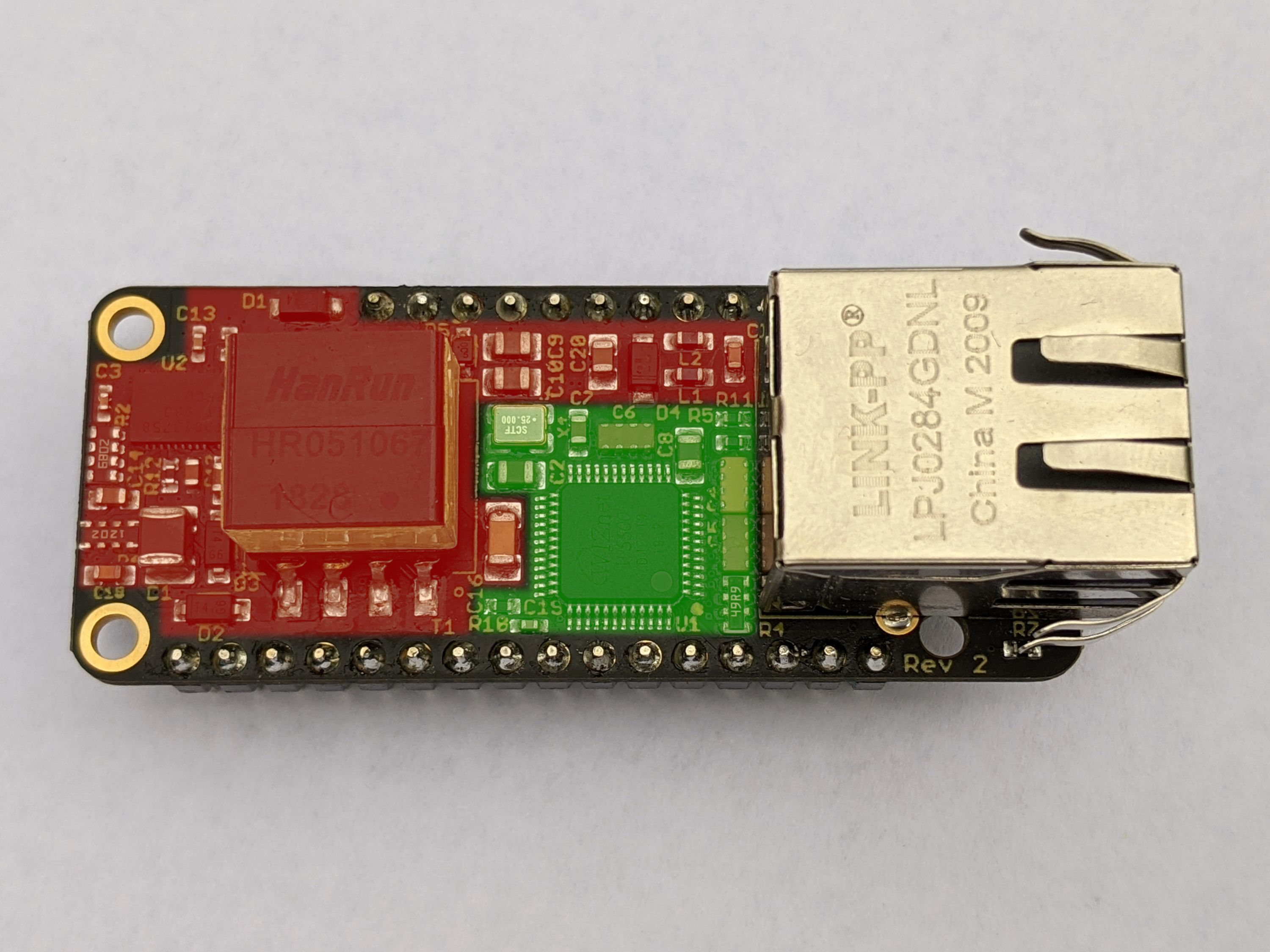
The area shaded in green is the Ethernet subsystem around the Wiznet W5500, pretty much what is on the Adafruit Ethernet FeatherWing, but shrunk down. The area shaded in red is the Power over Ethernet subsystem, which is capable of delivering about 4W of power, more than enough for a typical Feather system!