Project update 5 of 7
Reviving a Vintage Radio with Loud-ESP
by AndriyOne of the reasons I created Loud-ESP was to bring new life to old, obsolete audio gear. Some time ago, I bought a Unica Oscar 7015, a Dutch radio from the 60s. It looks brilliant but, despite having a great cabinet and vintage-sounding speaker, it is quite useless these days. Even if it was working, it would not be able to pick up anything in today’s digital airwaves and it would draw way too much power in the process. Just the idea of something made of wood and cardboard eating a few hundred of watts of power makes me uncomfortable.
But that’s not even the whole story. In the 60s and 70s it was quite common to skip using an input transformer to cut costs. They would just rectify mains voltage to use it directly for anode voltage. That means that if you plug it into the socket backwards (which way is backwards? the plug is symmetrical!), you’ll get mains voltage on the chassis. I’m sure this was fine by 60s standards, but I wouldn’t keep this widow-maker around the house in the 2020s.
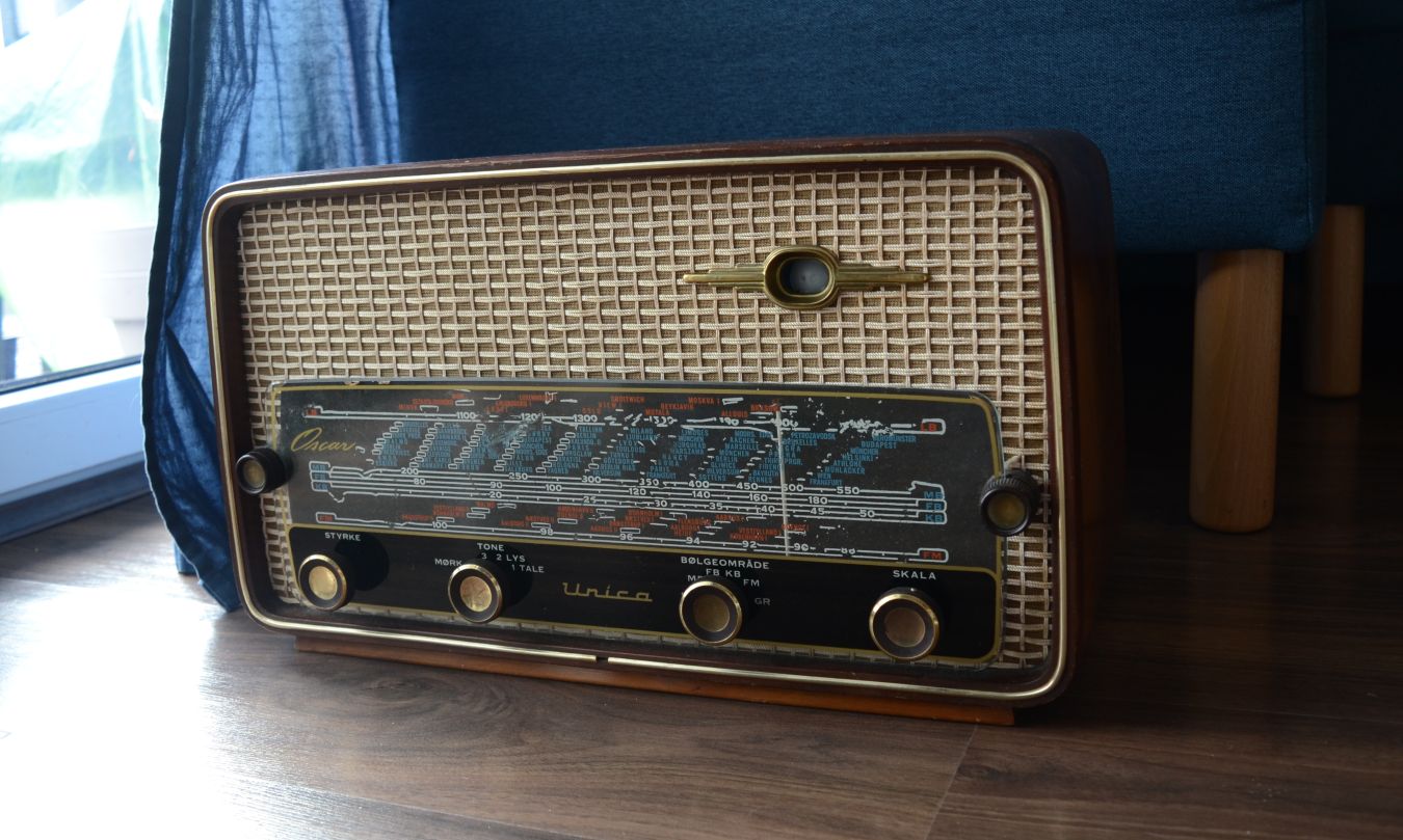
Consequently, I chose to eliminate the stock electronics entirely and just use what interests me: the cabinet and the speaker. These are the two main things responsible for the old-school sound I’m after.
Firmware
As I’m not particularly good at coding, I decided to use Ka-Radio32 project. Ka-Radio32 is a Wi-Fi radio project with support for IR remotes, LCD screens, and a few extras. It can run on the built-in DAC of the ESP32 as well as a few external DACs. It even has an Android app that works together with the ESP32. That makes it perfect to host on Loud-ESP.
First, I’m going to clone the repo
$ git clone https://github.com/karawin/KaRadio32_4
Since I already have ESP-IDF installed and imported, as described in the previous update, I can start building straight away.
$ idf.py build
Before we flash the firmware, we need to perform one additional step: the hardware configuration partition needs to be prepared. First, we add a csv entry to the configuration in the `boards/esp32-audio-e-240x320-touch.csv’ file:
key,type,encoding,value

label_space,namespace,,
L_LABEL,data,string,esp32-audio-e-mini.csv
L_COMMENT,data,string,ESP32 Audio Dev Board rev E

gpio_space,namespace,,
K_SPI,data,u8,2
P_MISO,data,u8,19
P_MOSI,data,u8,23
P_CLK,data,u8,18
P_XCS,data,u8,255
P_RST,data,u8,255
P_XDCS,data,u8,255
P_DREQ,data,u8,255
P_ENC0_A,data,u8,255
P_ENC0_B,data,u8,255
P_ENC0_BTN,data,u8,255
P_ENC1_A,data,u8,255
P_ENC1_B,data,u8,255
P_ENC1_BTN,data,u8,255
P_BTN0_A,data,u8,255
P_BTN0_B,data,u8,255
P_BTN0_C,data,u8,255
P_BTN1_A,data,u8,255
P_BTN1_B,data,u8,255
P_BTN1_C,data,u8,255
P_I2C_SCL,data,u8,255
P_I2C_SDA,data,u8,255
P_I2C_RST,data,u8,255
P_LCD_CS,data,u8,5
P_LCD_A0,data,u8,4
P_LCD_RST,data,u8,32
P_IR_SIGNAL,data,u8,0
P_I2S_LRCK,data,u8,25
P_I2S_BCLK,data,u8,26
P_I2S_DATA,data,u8,22
P_ADC_KBD,data,u8,255
P_ADC_BAT,data,u8,34
P_BACKLIGHT,data,u8,255
P_TOUCH_CS,data,u8,2
P_JOY_0,data,u8,255
P_JOY_1,data,u8,255
P_LED_GPIO,data,u8,255

option_space,namespace,,
O_LCD_TYPE,data,u8,194
O_LCD_ROTA,data,u8,0
O_LCD_OUT,data,u32,0
O_DDMM_FLAG,data,u8,1

custom_ir_space,namespace,,
K_UP,data,string,0xFE014F 0xFE0150
K_LEFT,data,string,0xFE0110 0xFE011A
K_OK,data,string,0xFE0113
K_RIGHT,data,string,0xFE0116 0xFE0118
K_DOWN,data,string,0xFE014B 0xFE0151
K_0,data,string,0xFE0101
K_1,data,string,0xFE014E
K_2,data,string,0xFE010D
K_3,data,string,0xFE010C
K_4,data,string,0xFE014A
K_5,data,string,0xFE0109
K_6,data,string,0xFE0108
K_7,data,string,0xFE0146
K_8,data,string,0xFE0105
K_9,data,string,0xFE0104
K_STAR,data,string,
K_DIESE,data,string,
K_INFO,data,string,0xFE010F
Next, we build an NVS partition and flash the ESP32 firmware:
$ cd board

# generate partition blob out of csv
$ python3 ./nvs_partition_gen.py --input esp32-audio-e-240x320-touch.csv --output ./build/esp32-audio-e-240x320-touch.bin --version v1 --size 0x3000

# flash at 0x3a2000, as defined in the partitions.csv file
$ esptool.py --chip esp32 write_flash 0x3a2000 ./build/esp32-audio-e-240x320-touch.bin

# flash firmware
$ idf.py build flash monitor
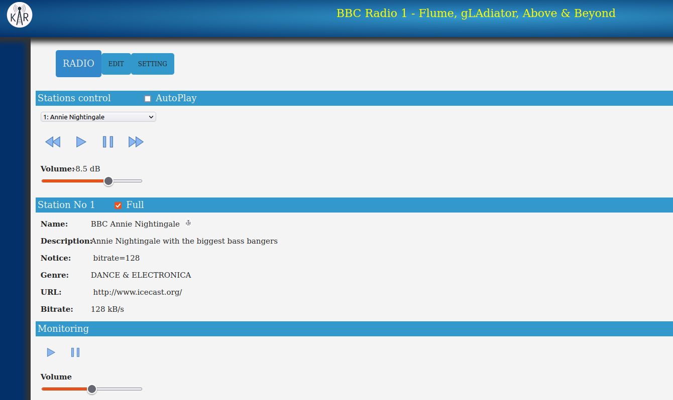
Next we need to set-up Wi-Fi credentials. There are a number of ways to do this, but the easiest is to run the wifi.con("ssid","password") command and restart. After that, amongst other information, the console will display:
##CLI.ICY0#: at IP 192.168.0.216
This is the web address for connecting a browser or the Android app to configure stations and control radio.
Mechanics
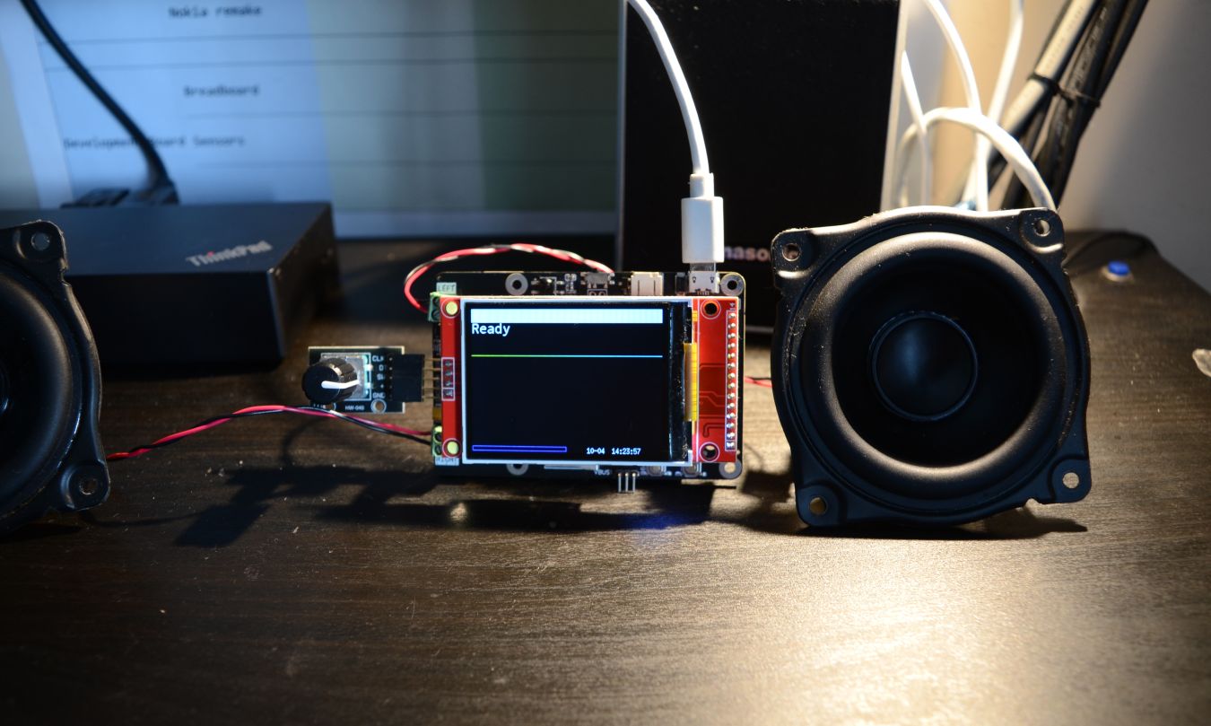
Since my radio has only a single speaker, I need to configure the DAC to work in mono mode. This is done by shorting a jumper on the board, which informs the MAX98357 chip to work in mono mode. While I will use only one channel, many old radios have two speakers so you can use both channels in that case.
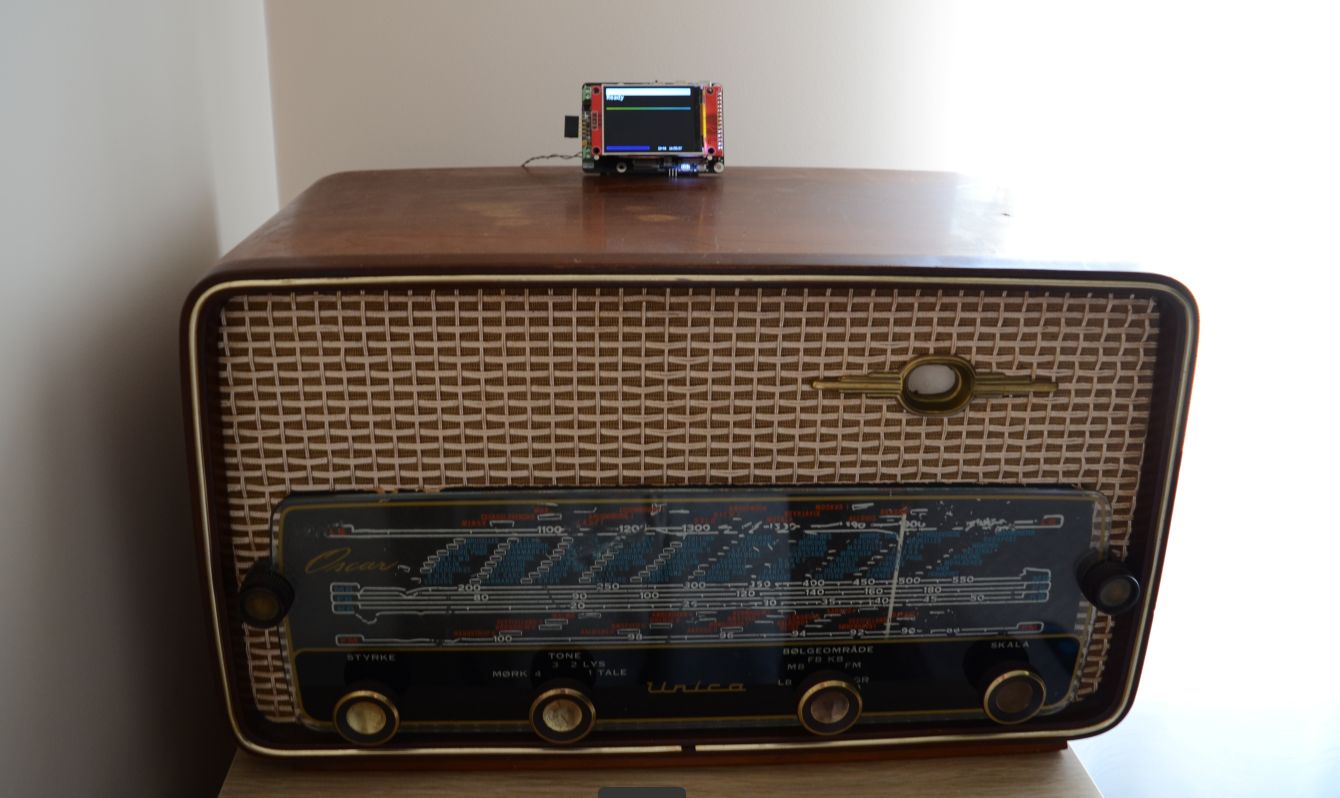
For this minimal setup, I just need to connect the speaker. But, since the IR input is configured already, why not to expose IR recevier, so I can control the radio via remote? You could also add a rotary encoder, a screen, and RGB leds if you feel like it, but that’s all optional of course.