Project update 5 of 14
CNC Machining & Other Features of the HQ-Camera Housing
by Eugene PomazovWhy Metal?
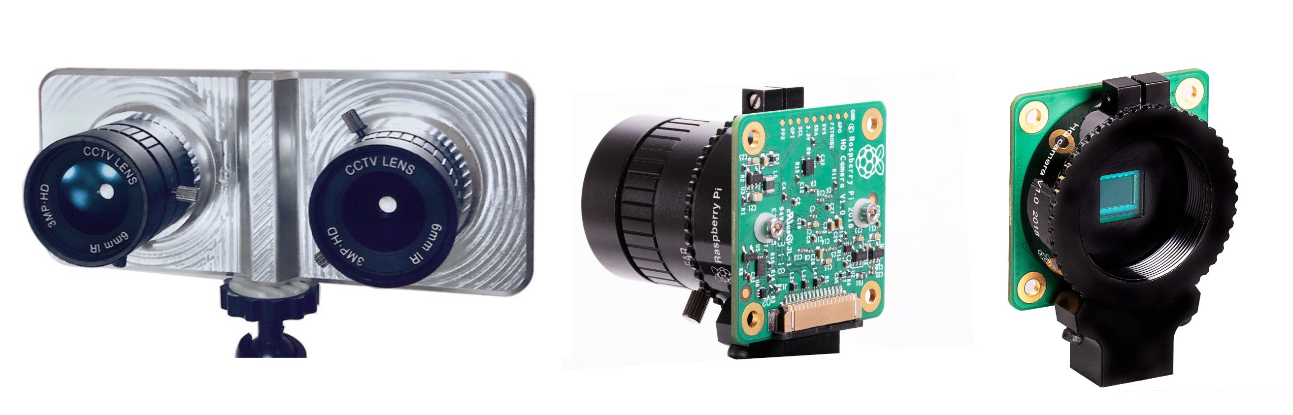
Last year, the Raspberry Pi foundation unveiled their new device, the Raspberry Pi HQ camera. It has a more powerful sensor, with 12-Mpix resolution, and is working with C/SC lenses (1" diameter). In comparison with the 1.5 mm diameter optics in the V1 and V2 cameras, this is absolutely another level! We wrote about HQ camera advantages in our previous update.
These advanced lenses are heavy-weight. For example, this 16 mm lens weights 175 grams! And you need two for the stereoscopic setup! If you install a pair of HQ cameras with this kind of optics using the plastic camera enclosure, you can run into some trouble. The main problem is that you can’t keep the cameras’ axes parallel. This issue is critical for computer vision, to prevent your setup from loosing its calibration. And if you are recording stereoscopic video, the last thing you want is for your axes to shift while you’re recording.
That’s why we developed this robust, light-weight, metal housing for a pair of HQ cameras.
CNC Magic
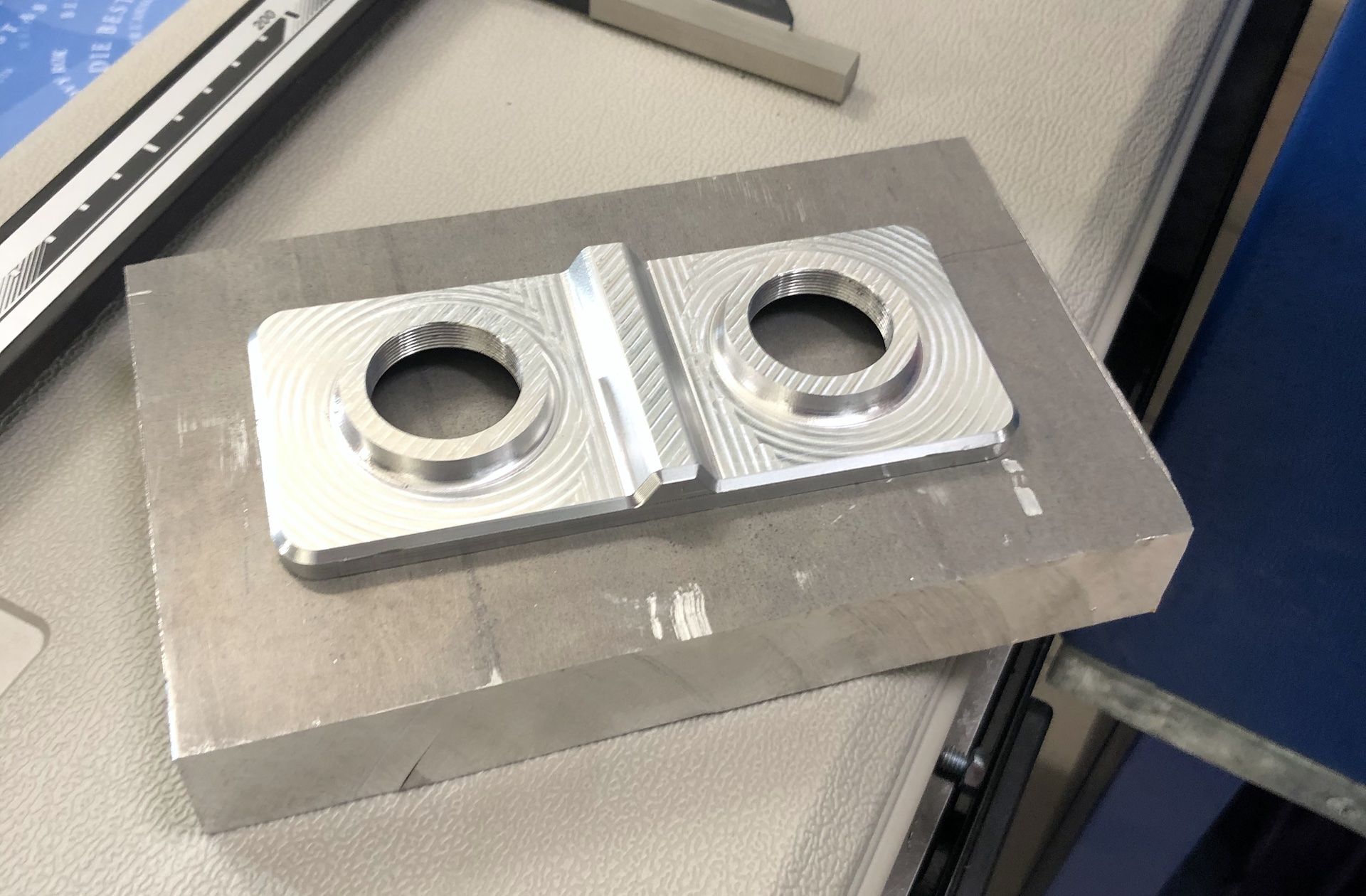
We choose the CNC machining approach for our first batch. In the image above, you can see the original aluminum plate on the bottom and the result on the top. CNC machining is a great technique for small batches (hundreds of pieces), and it allows us to fix design issues on the go. Ideally, we will switch metal casting at some point, as it’s more suitable for batches that involve thousands of pieces.
Here’s what the CNC-machining process looks like:
Fun fact: CNC machines use water cooling, so the whole protective-glass enclosure is covered with water droplets. To keep the viewing window clear, a rotating glass removes the droplets by centrifugal force!
For our prototypes we used 7075T6 aluminum (which is also used for aircraft). That’s right, StereoPi is ready to fly! :) We plan to use the same material (or perhaps 6061) in the production batch.
By the way, all of our images and photos shows non-coated aluminum. The production version will be anodized and black. This is not just for aesthetic purposes but to reduce light reflections in the space between the lens and the sensor. As you may have noticed, the original HQ-camera housing was also black. This was not an accident!
IR-Filter Feature
All modern camera sensors are able to see more that the human eye. They can capture ultra-violet light and a portion of the infrared range. But if you look at the result, you won’t like it.
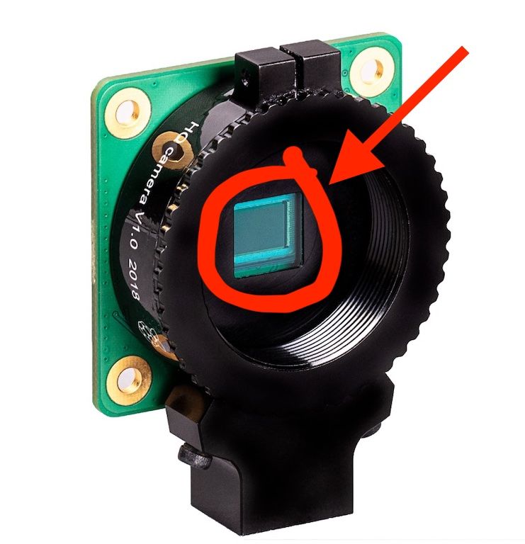
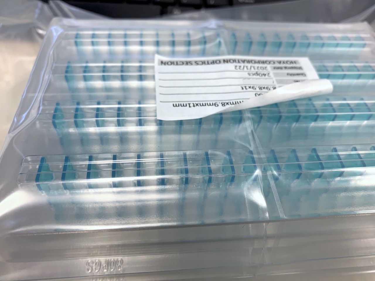
To remove this effect, manufacturers add special glass filters that suppress light in ranges that are invisible to the human eye. Here is the IR filter, used in HQ camera:
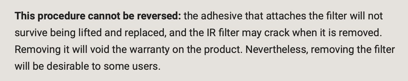
So, Houston, we have a problem. If we disassemble an HQ camera and put it into our HQ housing, we’ll have no UIR filter. It’ll still be sitting there inside the original HQ-camera setup! You can, of course, use brute force to remove the original IR filter. Raspberry Pi even has a recommendation and precaution for this in their HQ camera guide:
After carrying out this procedure, you would be unable to re-assemble your HQ camera. But don’t worry, we came up with a better technique. We contacted the Raspberry Pi Foundation, and they introduced us to the HOYA corporation, which produce these filters. We ordered the same CM500 filters for our HQ setup.
You get a couple of these filters with your HQ housing, which means your original HQ camera will remain in good shape with it’s original filter. You can always remove the guts from our housing and re-assemble the stock version!
Vertical-Adjustment Trick
No two things in this world are identical. If you take two sensors or two cameras, they are bound to have some assembly differences—usually at the scale of a tenth (or even a thousandth) of a millimeter. But for a 12-Mpix camera sensor with a 1/2" diagonal, such tiny differences translate to real pixels on in your stereoscopic photo! Look at this image:
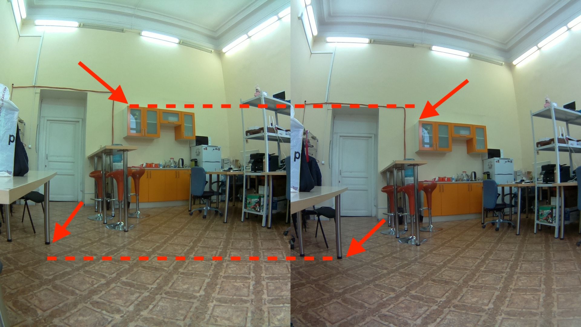
Sure, you could post-process this image (using StereoPhoto Maker, for example), but you’d lose a portion of the image after cropping. And besides, one of the most important use-cases here involves real-time, livestreamed video to a VR helmet, which means you can’t necessarily count on professional-quality hardware for on-the-go image processing.
To address this challenge, we added a simple-but-effective feature that allows you to calibrate the vertical alignment of each camera. As a result, you don’t need to use a powerful desktop computer or hard-core production equipment to fix your vertical alignment in realtime.
To explain how this works, we made the following short video without cameras installed.
Essentially you have a regular screw on top and a ball plunger—a tiny steel ball with a spring under it—on bottom. This allows your cameras to remain stable when you use the top screw to make delicate adjustments to your camera’s vertical alignment.
And, of course, we’ve included all necessary screws and ball plungers in the HQ housing kit! :)
Stay tuned!