Project update 4 of 11
Design Tweaks & Procurement Challenges
by Daniel GHi!
Well, the TinyNES is actually going to happen now that we’ve more than doubled our campaign goal! This is so awesome! Thanks everyone for your support and for finding this little project interesting. We have more surprises in store too!
For this update, I’m going to talk a little about some of the weird details of trying to make electronics right now, how the global chip shortage has and hasn’t impacted this particular project, and what it looks like to tackle some DFM (Design For Manufacturing) details. Maybe this stuff is too wonky for most people? You decide…
Tweaks and More Tweaks
Designing a circuit board has several steps:
- Choose the components. What kind of parts or chips or switches or lights does your circuit need?
- Draw the schematic. This defines the circuit and how the components are electrically connected to each other. It usually has very little to do with the physicality of the parts or the board.
- Create the component footprints. Each component that will be soldered to a circuit board has a particular set of precisely shaped pads or holes that it needs to land upon. These can be created from part datasheets and sometimes downloaded. I like to make them myself.
- Lay out the board. How big is the physical circuit board going to be and what shape? How many layers will it have? Where are the major components going to be placed and how will they be oriented? This is kind of like figuring out where you want your furniture to go in an empty room.
- Route the board. This involves drawing all the little traces running between the components. Most software for doing this knows about the schematic, so it can help show you what needs connecting and if there are any mistakes. This is kind of like decorating your room once the furniture has been moved in and arranged.
- Get/make the board! This is the exciting and/or disappointing part. Most of the time (but not always) a factory will manufacture your board for you. Then you get to decide if you want to do all the soldering yourself or if you want to pay the factory to do that too.
That’s it! There can be a lot of going forwards and backwards between these steps, including going all the way back to the beginning multiple times (changing components) and going all the way back to the end multiple times (prototype revisions). This is all part of the fun! Well, hopefully it’s fun. Otherwise you should probably have a different hobby and/or job, if you can afford to.
Then, when and if you finally want to go from making one or two of your board, to making tens or hundreds or thousands, a new set of challenges arises. This is sometimes called Design For Manufacturing, or DFM, and this is an interesting process in the best of times and an even more interesting process during a global chip shortage!
Empty Shelves
From my (limited) point of view, the chip shortage has mostly affected the supply of 32 bit microprocessors, things like STM32s and other ARM chips that are used in cars and smart appliances and just about everything else. Chip fab capacity is limited though, so when demand outpaces supply for things like this, it can have second-order effects on less-popular chips that still rely on the same fabrication plants.
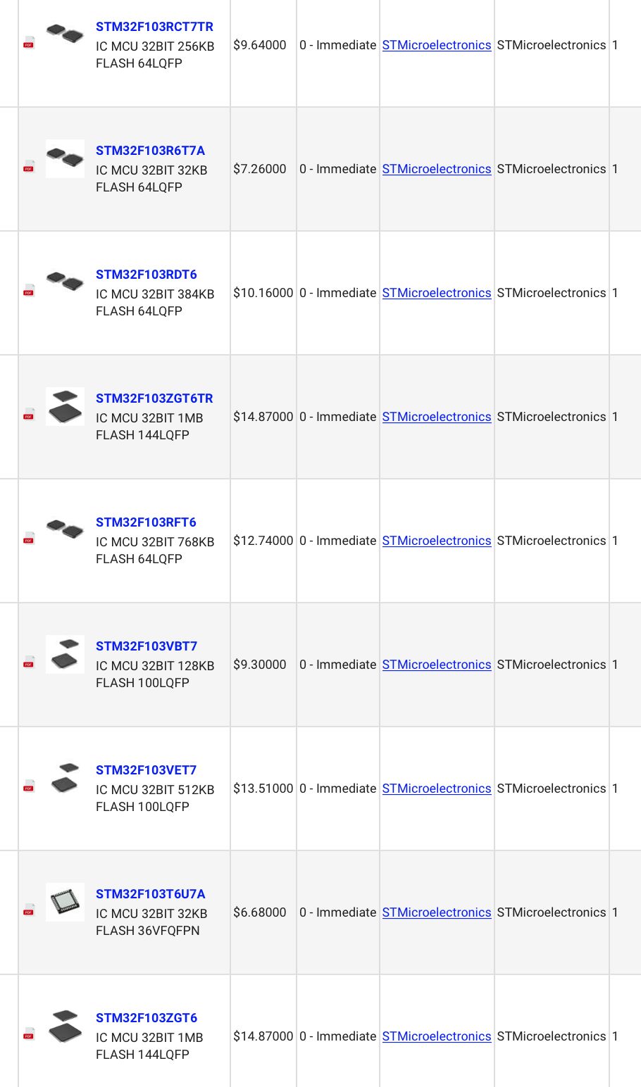
All this is to say, I’ve never seen so many sold-out components on Digi-Key! It’s something new. Well, not entirely new. A few years ago it was almost impossible to buy a 0.1 µF capacitor for a little while. Now, there are millions of them in stock. These things happen and they seem to come in waves. This just happens to be a pretty big and long lasting wave, for a number of different reasons (COVID-19 being one of them).
Avoiding Unobtainium
Generally, you don’t need to worry too much about certain details when you’re making a one-off board or building something quickly from parts you already have lying around. However, when you want to produce a lot of something, you have to start worrying about things like:
- How many of each component do distributors currently have in stock?
- When they run out of stock, how long will I have to wait for the manufacturer to make more?
- Does my design rely on any parts that can't be replaced with other similar parts?
- Am I ignoring any de facto standards that will make replacing parts harder later on?
- How much is each board going to cost and will alternate parts cost a lot more?
- Are the parts that I'm relying on active (still being manufactured) or not?
Example One: The Clock
The NES relies on a master clock. A clock is basically just a 50% duty cycle square wave at a particular frequency that multiple parts of a system rely on. The NTSC (as opposed to PAL) NES requires a 21.477270 MHz (very specific!) clock. Traditionally, this clock signal has been generated with a crystal (made of quartz) that’s cut to resonate at the desired frequency. Over the years, the necessity of this particular frequency of crystal has waned and so, starting a couple of years ago, you couldn’t really buy one anymore.
The first TinyNES revisions all used crystals, with a circuit to energize them and amplify their vibrations, but when stocks ran low, it was time to change the design. We could have focused on sourcing all the 21.477270 MHz crystals we could get our hands on or we could have approached crystal manufacturers about producing a custom part for the TinyNES, but instead we decided to change the clock source entirely, to something called a MEMS oscillator. MEMS stands for "microelectromechanical system." These devices can be programmed to run at a particular frequency. So cool!
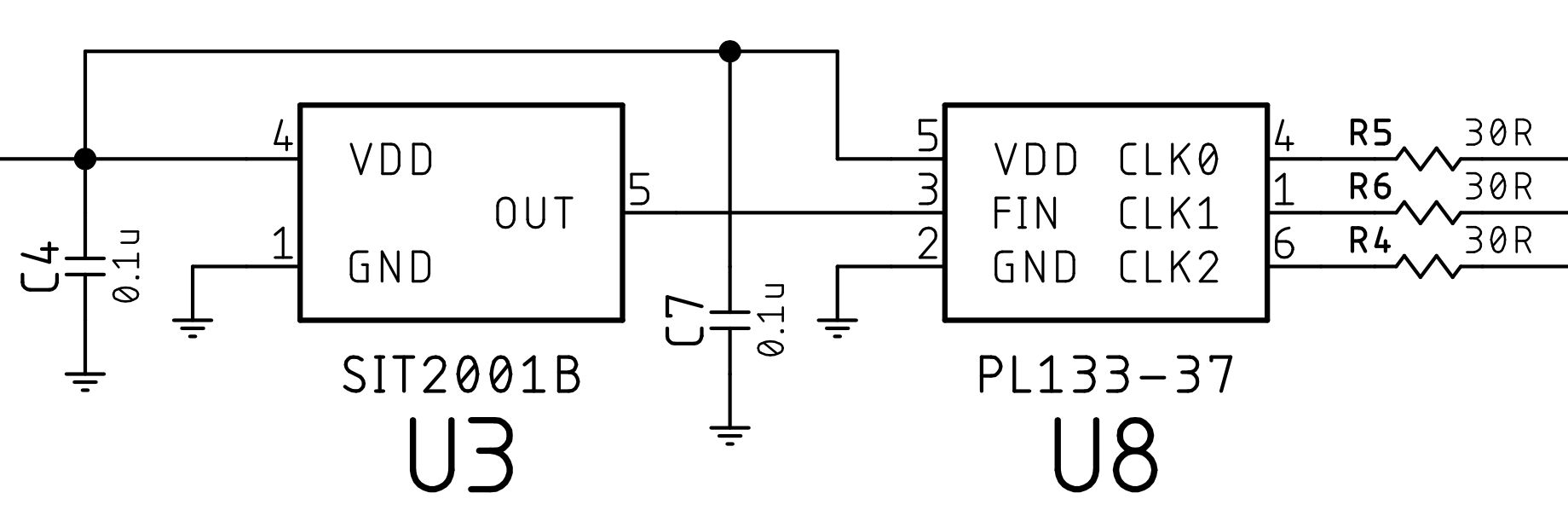
Using a MEMS oscillator required redesigning the clock circuit, which meant getting rid of a whole bunch of components and replacing them with new ones, like a little 3.3V power supply for the MEMS chip and a buffer to feed the clock signal to the various system components.
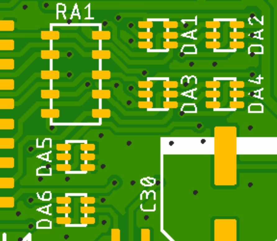
Example Two: Diode Arrays
The controller signal lines in the TinyNES have a whole bunch of protection diodes on them, which help to prevent any problems related to plugging and unplugging controllers while the system is powered on. It has so many diodes that I decided to use several diode arrays instead of tons of individual little components. This would save space and reduce the overall number of parts. I found some diode arrays that looked good and didn’t think much more about it.
But now, these diode arrays are gone! Out of stock. Poor Toshiba 1SS309. This happens. But the mistake I made was not looking carefully enough to see what most diode arrays on the market look like. If I had, I would have noticed the ones I chose were weird, and weird isn’t good when it comes to finding a replacement. For something like this, the most important traits are the pinout (which pin does what) and the package (what shape the little chip is).
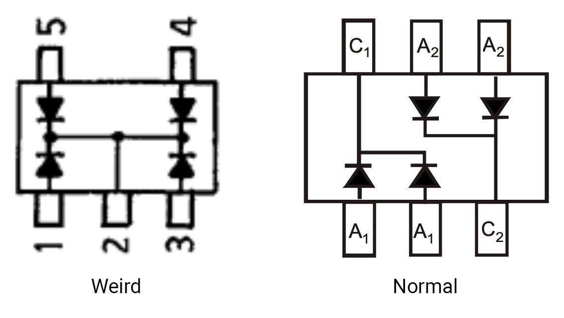
What I should have done is looked to see what most diode arrays look like and how big they are. What I would have found is that the vast majority of diode arrays are arranged as two sets of pairs, with one extra pin, in a SOT-363 package. This makes them slightly more versatile. If I’d done this, then all I’d have to do now is pick a new one from a different manufacturer, but instead the board itself had to be changed.
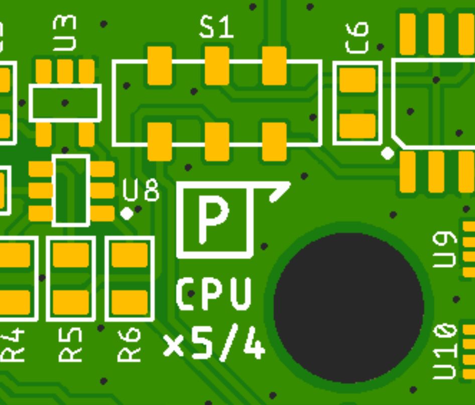
Example Three: The Fancy Sold-Out Switch
When I added the 1.25x CPU clock circuit to the TinyNES, there needed to be some way to switch it on and off. This sounded like a job for… a switch. The switch is inside the device, so you have to open it up to change it. This is intentional. I don’t want it accidentally getting bumped and underclocking your UA6527P system.
When I built the circuit, I thought something along the lines of "this should be a low-profile teeny surface-mount DIP-switch sort of thing" so that’s what I went looking for, and for some reason, I selected the Nidec Copal CAS-220TB, a $1.40 extravagance that’s so small you need to use tweezers to flip it. Oh, and now it’s out of stock.
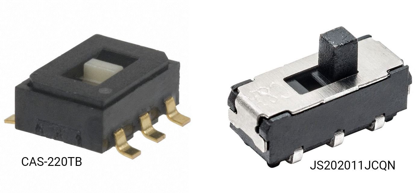
In the time since then, in other projects, I’ve discovered and used the lovely little C&K JS202011JCQN. It’s less svelte, much less expensive, and way more available. This change, of course, required even more board tweaking.
A Change In Power
Someone on Twitter said they thought the TinyNES should use a USB-C power cable instead of a barrel jack. My first instinct was this was nonsense. The last time I thought about it, I decided power via USB was somehow inelegant. The TinyNES doesn’t communicate over USB after all, so why use a USB connector? Aren’t USB-C jacks expensive? Aren’t USB-C cables expensive? Why use a connector with 24 pins when we only need one with two?
But over the past week, I’ve thought about it more and more. And I’ve come around to the idea! There’s not one good reason to use USB-C, there’re actually a bunch of good reasons:
- Barrel jacks come in a bewildering number of sizes, none of which are compatible with each other.
- Even the most common barrel jack, which is 2.1 × 5.5 mm, is annoyingly similar to the almost-but-not-quite the same 2.5 × 5.5 mm barrel jack. They're incompatible of course.
- Most devices that use barrel jacks are center-positive, but not all of them! Namely guitar pedals, which often have center-negative barrel jacks. What a world this is!
- There's no voltage standard for barrel jacks. Power supplies that output anything (e.g., 5V, 9V, 12V, 15V) as DC or AC might use the same barrel jack. Plug the wrong one into the TinyNES, and it might fry something (I have actually done this).
- The USB-A to barrel jack cables we were planning to include are already kind of an inelegant hack.
- These days, most people are likely to already have USB-C adapters lying around.
- Likewise with USB-C cables.
- You can buy USB-C "power only" jacks, and they're not expensive. They only have six pins (two VBUS, two GND, CC1 and CC2). This is actually kind of... elegant?
- USB-C adapters and cables aren't significantly more expensive than USB-A adapters and USB-to-barrel cables.
- USB-C adapters and cables are significantly more versatile than the above.
- USB-C provides a guaranteed 5 V (without a PD handshake) so there's no risk of the wrong voltage.
- USB-C has no risk of the wrong polarity (e.g., center-negative vs center-positive).
- USB-C can be inserted either way. Ok, this isn't an advantage over a barrel connecter, but it is an advantage over USB Micro-B, which I kind of hate (I'm looking at you, NES Classic).
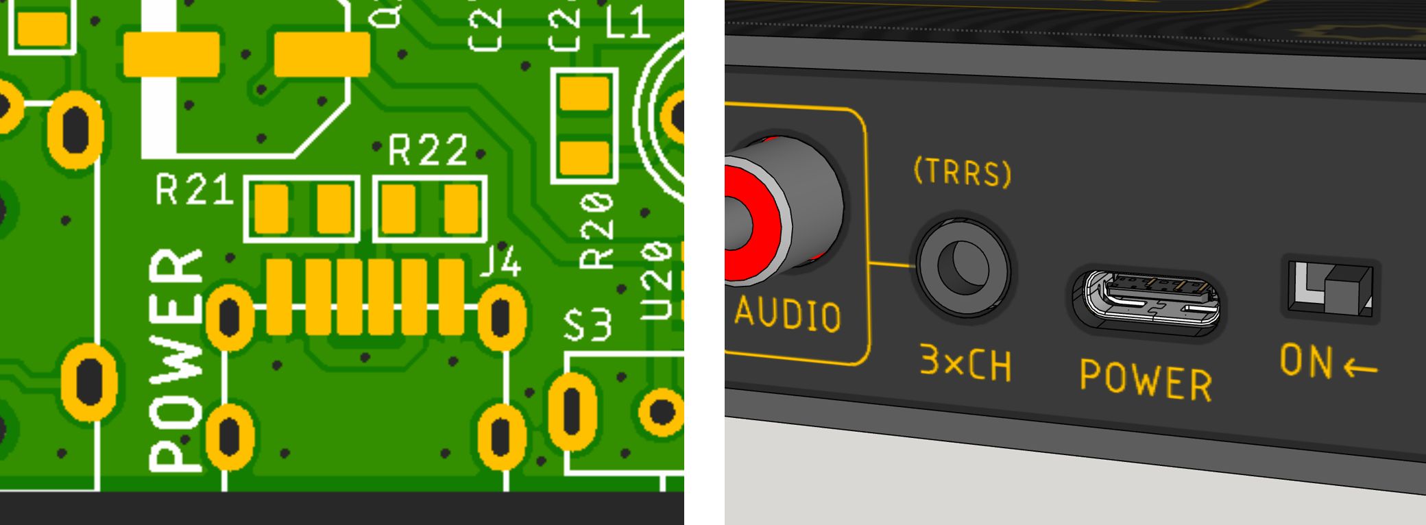
- There's room in the TinyNES to easily remove the barrel jack and replace it with a USB-C jack (and the two little resistors it needs).
And so, the TinyNES shall have a USB-C jack instead of a barrel jack for power. It will include a USB-C wall adapter and a regular USB-C cable.
And that’s that.
At least one person on Twitter will be happy!
Dan