Project update 25 of 38
Field Report Follow-up: Making a Case for Stereomaton
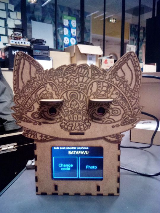
by Jack DesBwaEvery year, the HAUM hackerspace non-profit is invited to present some of our projects at the Festival Teriaki music event in Le Mans, France for which we create interactive installations. This year, as described in our previous Field Report, we used a StereoPi camera to create an itinerant, self-service stereoscopic photo automaton… a Stereomaton. Visitors use the Stereomaton to take photos of themselves and then view the results in 3D.
This big project required us to overcome a lot of challenges, such as designing a user interface, processing images for enjoyable stereoscopic result, handling file transmission with intermittent connections, showing the images to the public, and so on. Among all these big and small challenges, we also had to create a practical and appealing case. This Field Report will focus on the design and production of the case.
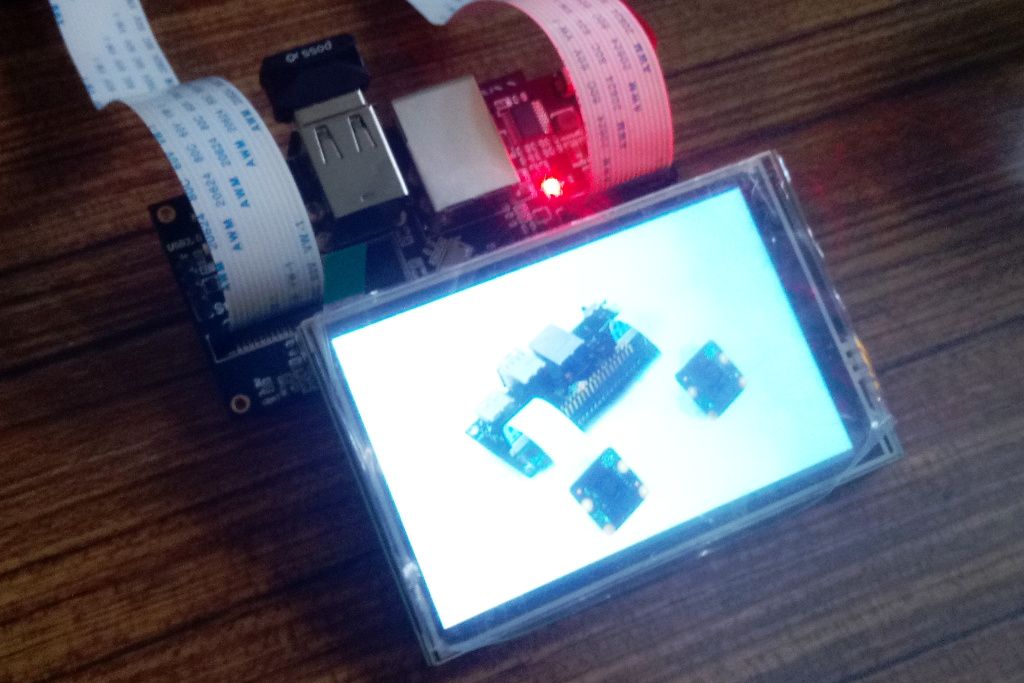
Let’s start at the beginning. To interact with users, we added a screen and touch-screen to the StereoPi. However, because of the camera ribbon cables, the extension connector of the board is turned around compared to the standard Raspberry Pi. The screen originally designed to cover the Raspberry Pi is consequently pointing outward:
Thus, we needed to design a custom case. We chose to make it using laser cutting technology because it is available in our workshop and it is fast. This method allows to cut flat materials (a few millimeters thick) with precision by projecting a powerful laser beam which will heat and vaporize the material to cut or engrave it depending on the power applied. Typically, we use affordable three millimeter MDF (Medium Density Fibreboard), although it is also dirty to work with. Obviously there is no volume, so several pieces need to be cut and arranged wisely in order to create three-dimensional objects.
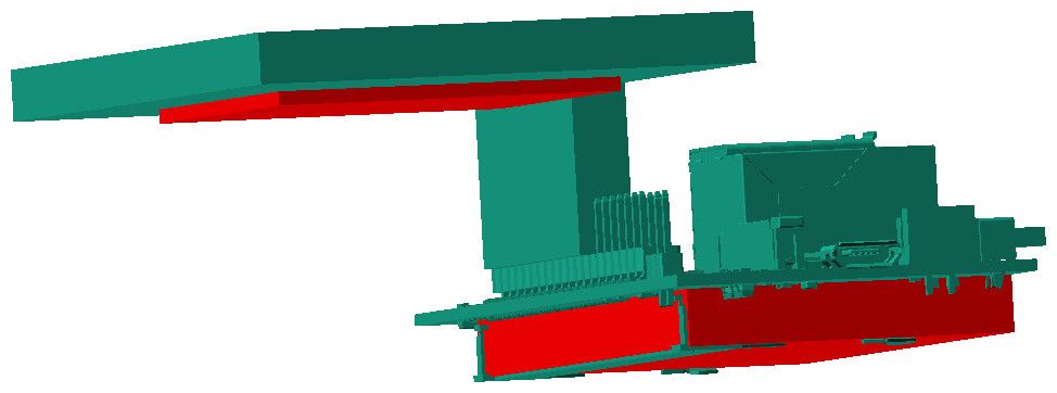
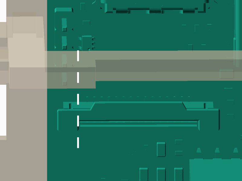
To minimize errors, a model of the assembled screen and StereoPi was first created. Note that the red zones are added where free space has to be maintained, mainly because of un-modeled components.
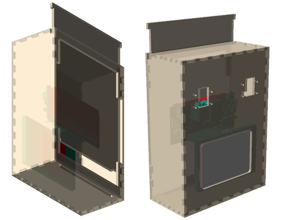
The first step is to design the outer box. Because the cameras and the screen need to be on the same side for this project, the two holes (and eight mounting holes) for the cameras and the one for the screen will all be on the front face. Note that some room is needed above the cameras for the ribbon cables to bend, and some room needs to be left under the screen for aesthetics. The other faces will be plain, except for the back which will have a sliding access door, just in case we would have to do some maintenance.
In order to assemble the box, some notches are added on the periphery of all pieces so that they can slot together. The notches are slightly smaller than their counterpart tabs to compensate for laser width and to get an interlocking pattern that locks without glue. The sliding door is made with plain material with a wider part on the top to stop it, and a smaller part on the bottom to enter into a long groove made on the bottom face. Of course a long groove is made on the top face too. Two small parts are also present behind the sliding panel to ensure guidance and solidity. The door will stay closed by gravity. Here is the result:
In reality, of course, the electronics cannot float in midair as shown. Some brackets will have to be added to support them.
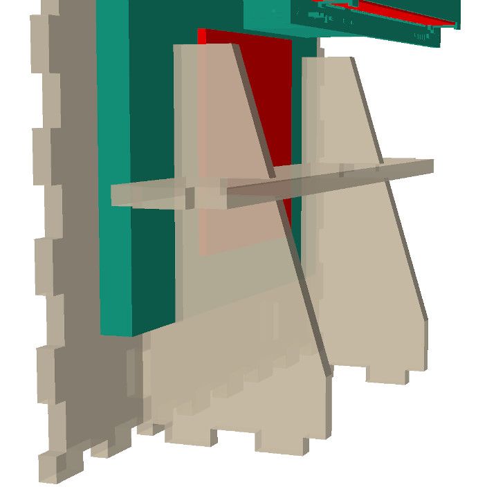
The screen will be placed on two spacers to support it at the bottom and two pillars will prevent it from rotating, especially when the screen is touched. These two functional parts are merged so that there are two pillars with spacers. A third piece connects the pillars together and is also slotted into the sides of the box for better stability. There is a gap between the pillars and the screen for compressible, protective material. This is to support and protect the screen without subjecting it to damaging stresses.
Although the StereoPi is linked to the screen by the connector, it is better to support it as well. For that, a simple bracket is placed just behind it. This bracket has a large hole for ventilating the compute module and another one to let the power cable pass through. Of course, there are also four holes to screw down the StereoPi with compressible spacers to adjust the distance with precision, again without placing damaging stress on the StereoPi.
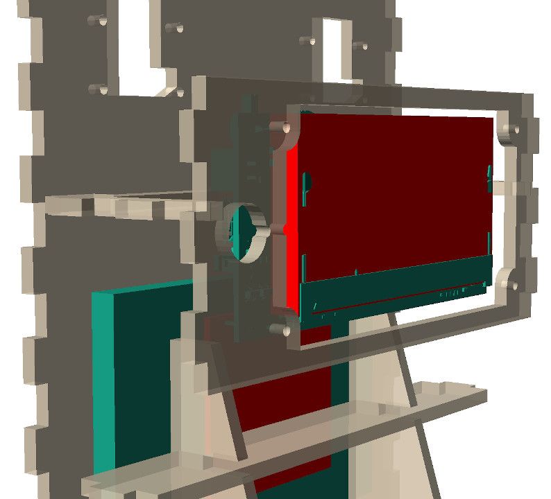
In these screenshots, you may have noticed two small slots on the StereoPi holder. These are designed to have a string tied to them. The other end of this string is attached to the power cable with a clove hitch, so that the string is far shorter than the remaining cable on the board side. Here is the trick: if the power cable is pulled too hard, the string tightens and takes the tension instead of the connector!
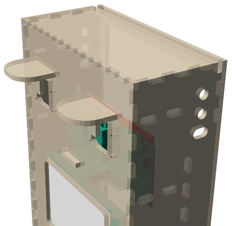
To complete the design, we’ll add two visors to protect the cameras from the sun, and add a few more holes. One of these holes will let the power cable out and the others can be used to hold the case or attach it to other mechanisms.
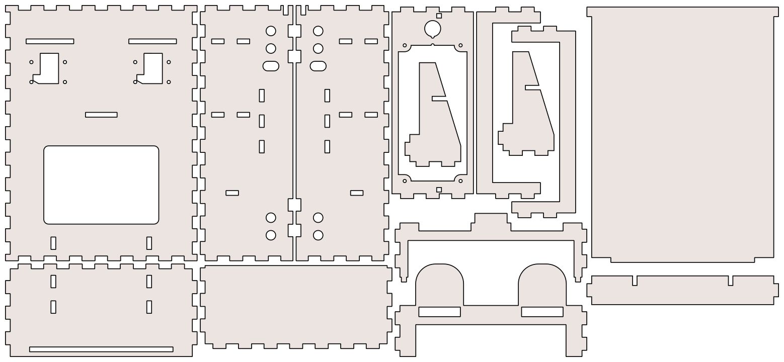
The case is now finished. Here are all the pieces to cut:
But wait… working designs are nice, but beautiful working designs are far better!
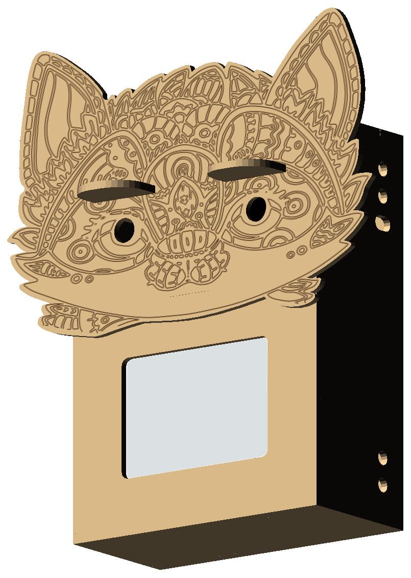
That’s why there is one last step to take in the creative process: add a decoration. The visors and the tongue made to slot into the StereoPi holder on the front face can help support a decorative mask. As a bonus, this mask will also hide the screws used to fix the cameras and can be changed easily. We found a beautiful, widespread drawing, which we could use to create a nice shape to cut. In addition, to make it a more beautiful mask, we recreated and adapted its decorative patterns in vector format so that the head of the laser can follow their mathematical paths to engrave them into the plate. Now, we add the mask to the previous parts. And voilà!
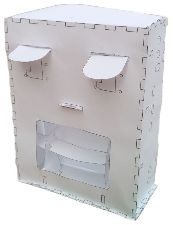
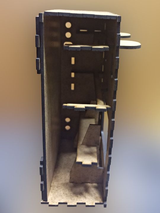
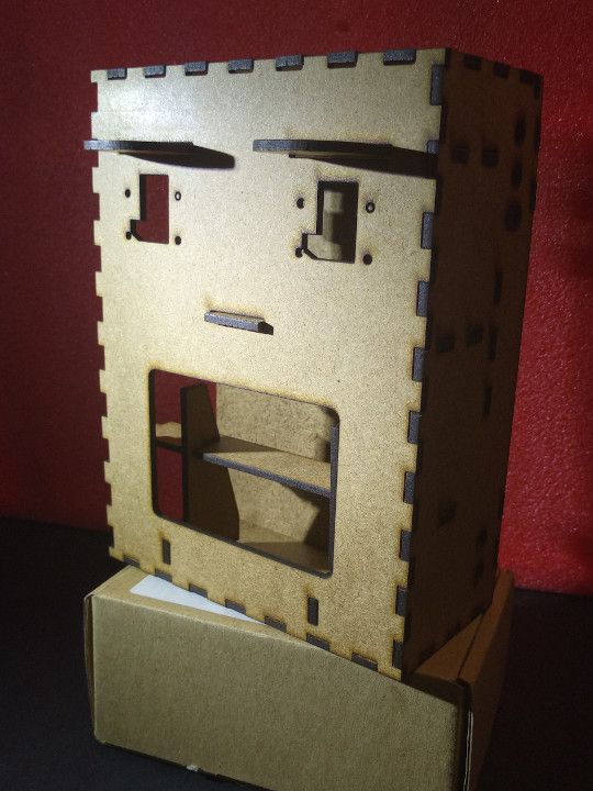
Before actual cutting, we assembled a paper prototype to check the design. It showed a small error: due to asymmetry created by the screen, a slot to allow the passage of ribbon cables was slightly too small for one side. By removing the front face, this error can be seen on the model too.
After correcting for this, we launched the laser cutter.
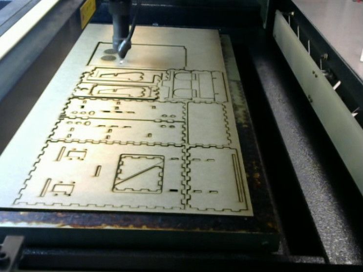
As you can see from this partial assembly, the pieces work well together.
We can take this project a little further…
- The case can be modified to adjust for a particular situation. For example, the bottom can be changed to add screws for mounting the case to a bar.
- There is some room inside the case to add a small battery. For larger batteries, a basket can easily be designed to be placed on the top of the box.
- Several masks can be created to change the look depending on the project or the mood.
- Et cetera... Your imagination is the biggest limit!
With the current design, the electronics are enclosed and cannot be removed easily, so some parts should probably be redesigned. But the festival was only a few weeks after the case was cut and there were many other aspects to manage, so this one will do for the project.
The plans can be found at https://github.com/haum/stereomaton/tree/case_article/case, although they may be modified with the next iterations of the prototype. However, the above link points to the specific version used in this article (including the correction discussed), so you can explore the history if you want to see further updates.