ZSCircuits
Test Equipment
Mouser Electronics
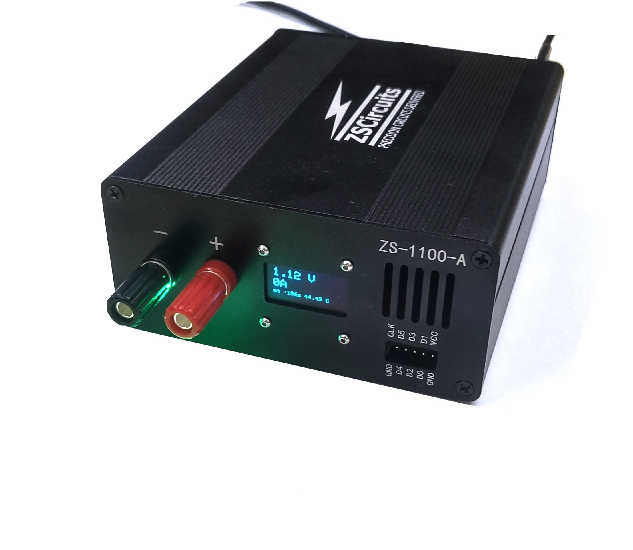
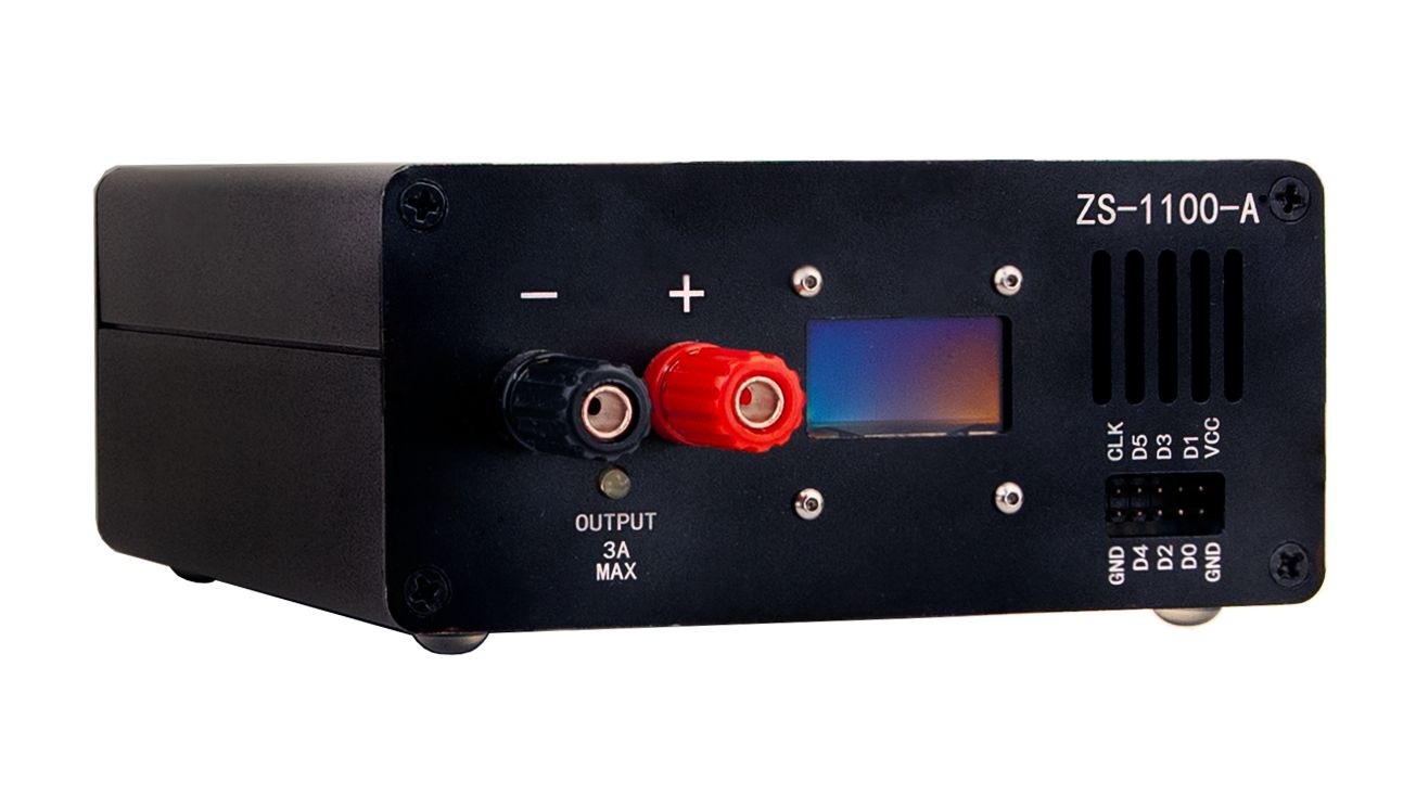
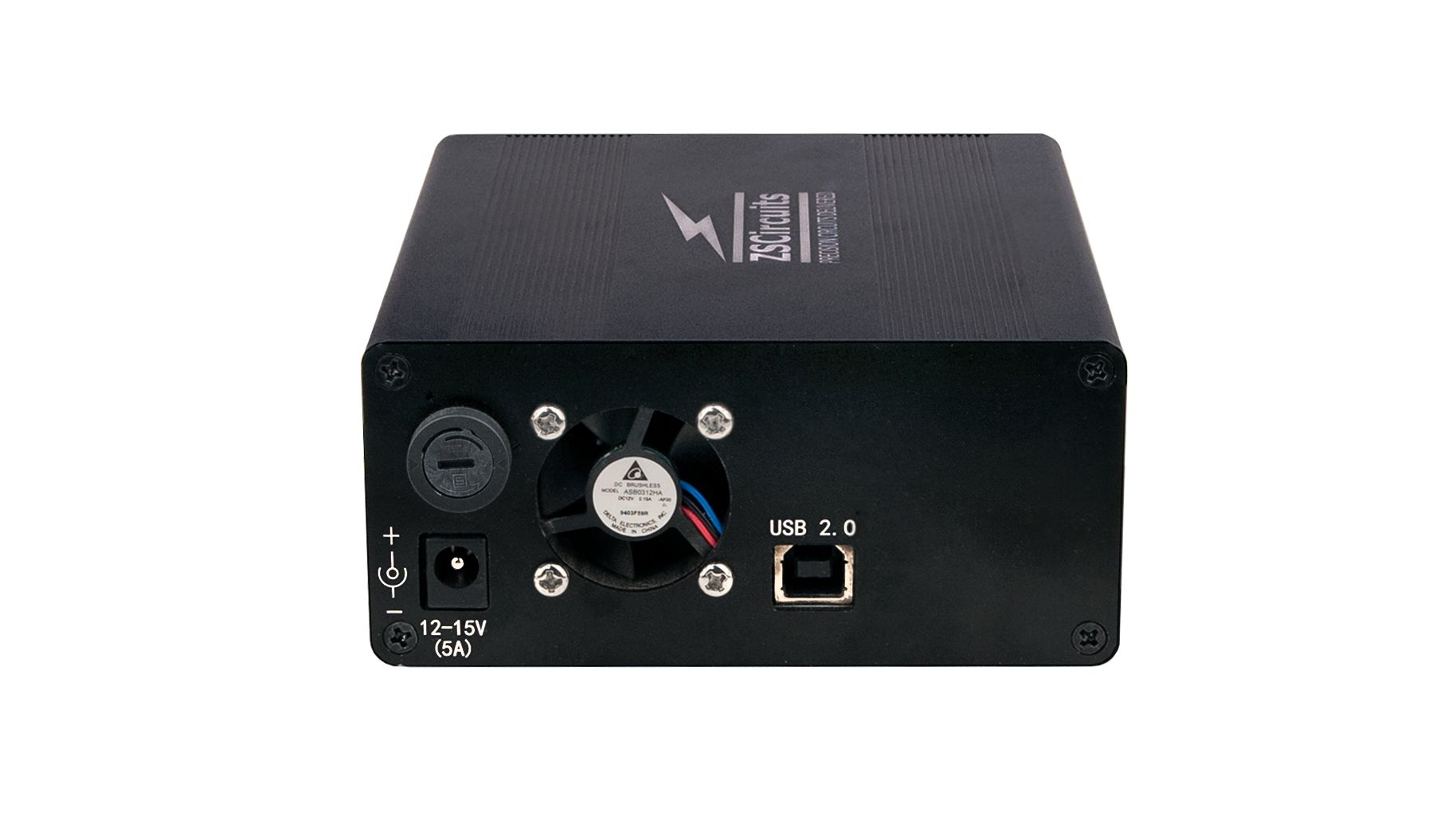
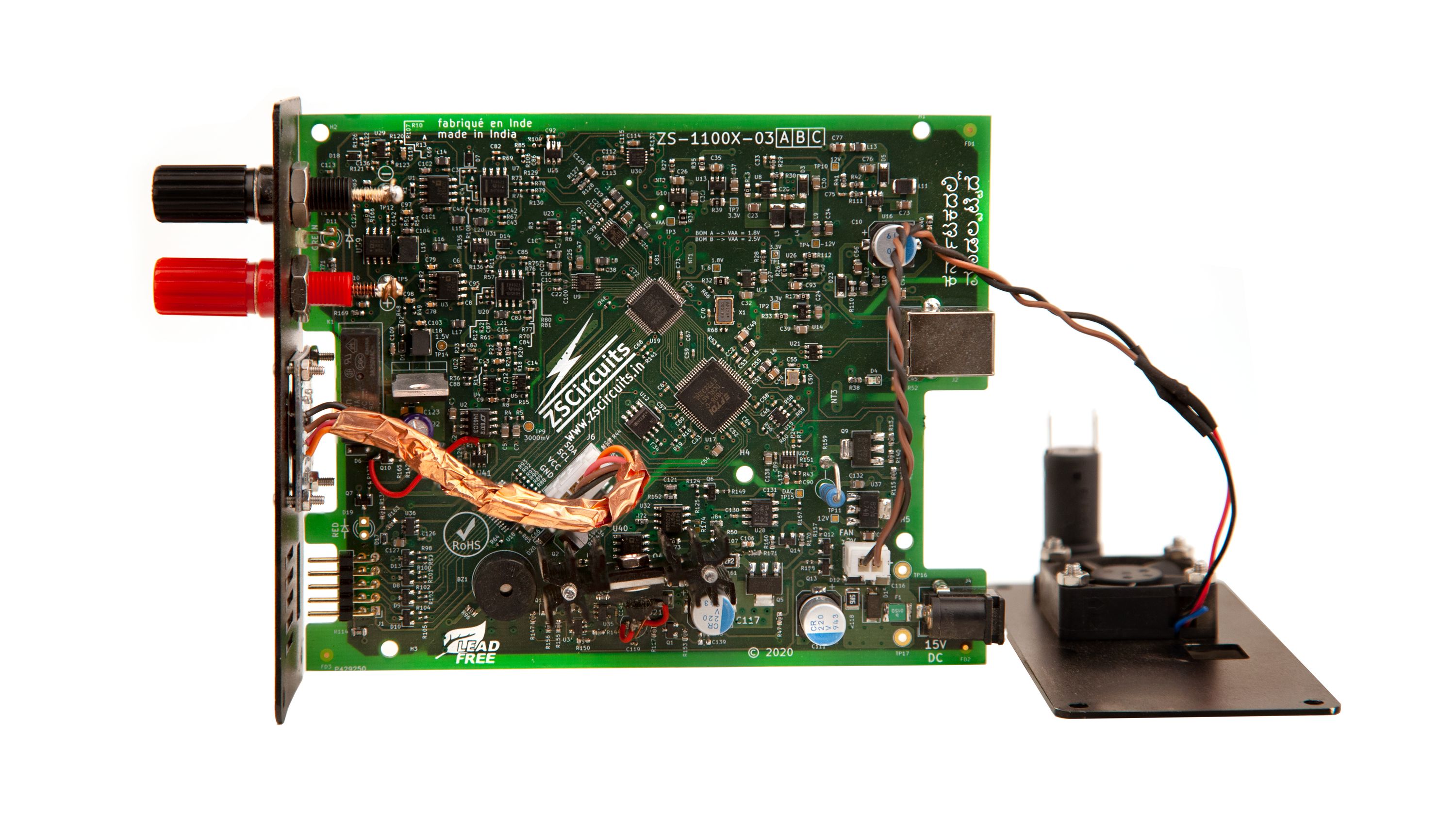
ZS1100A Power Meter
A USB-based power supply that can accurately estimate the energy consumption of IoT devices
ZSCircuits
Test Equipment
Mouser Electronics
Internet of Things is a leading buzzword these days in the technology world. Most of the devices used to create the IoT (Internet of Things) work on small batteries. The measurement of energy consumption of these IoT devices is a difficult task due to the dynamic nature of the current consumption. Developers often need to use multiple instruments and hand calculations to arrive at an estimate of the energy consumption. To solve these problems, the ZS1100A Power Meter has been designed. This tool can plot the current consumption vs time very accurately and in great detail, which can be used along with the battery model to estimate the overall battery life. It has been created by engineers for engineers.
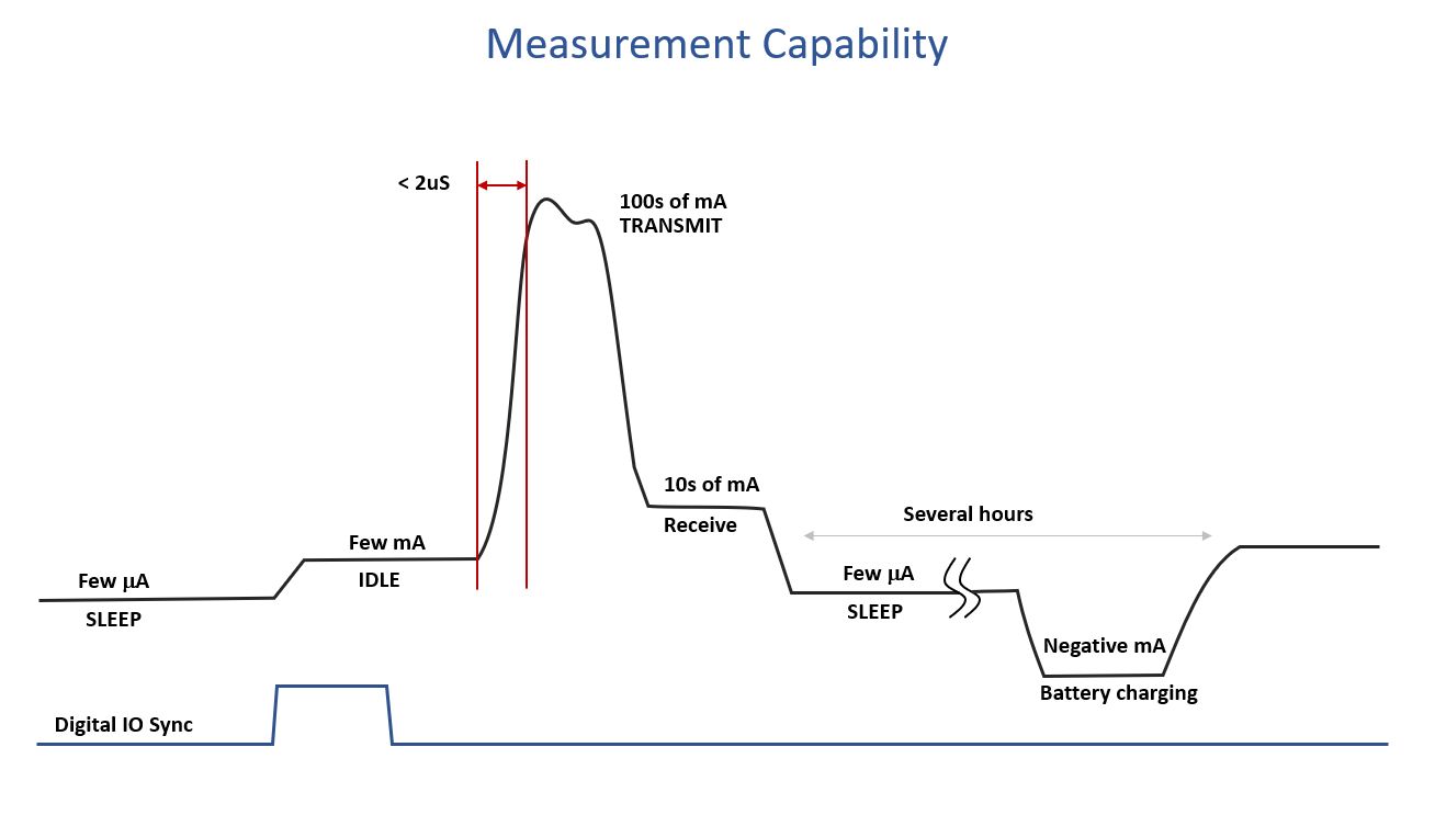
The power consumption of IoT devices follow a peculiar pattern which is difficult to measure using traditional equipment. The main reasons for this are listed below:
High Dynamic Range: An IoT device would consume a few μA in sleep state and few hundred mA in its transmit state, depending on the radio. Thus, the current waveform has a very high dynamic range spanning almost 6 decades.
High Bandwidth: The current drawn by an IoT device can change from few mA to hundreds of mA in couple of micro-seconds. Thus, the frequency content of these current waveforms is well over few 100 KHz.
Long Profile Times: It is not uncommon for IoT devices to have a typical profile which can last for several tens of minutes to 1 hour. They may perform intermittent wake-ups during this time for some misc activities, and hence these also need to be recorded. For accurate power analysis, complete capture of the profile is needed.
Multimeter: Most multimeters use range switching to achieve high dynamic range. While measuring the current, they introduce series resistor and measure the voltage across it. While measuring μA currents, the multimeter would add a few Ωs (may be kΩs) of resistance in series. If the IoT device performs a wake-up during this state, the drop across the high resistor can cause the device to trip and cause system reset. Most multimeters made for this application can record profiles for only few minutes. An IoT current profile can last several tens of minutes and hence the software on the IoT device may need to be modified to account for the limited capture time. Most multimeters do not have a full function GUI to measure various pulse parameters. The multimeters with digitizer options are expensive with retail costs starting at five thousand dollars, and often significantly higher.
Oscilloscope: Using a scope with a current probe is good enough to measure higher currents in idle and transmission modes. The sleep currents, which are of the order of few μA, cannot be measured with this due to the limited dynamic range. It can either measure high currents or low currents at a time. Most scopes use an 8- to 12-bit ADC and this limits the overall dynamic range. The capture length limits apply to most scopes and the overall solution is very expensive - at least few thousand dollars for the probe and tens of thousands for the scope. These limitations call for a new approach : ZS1100A Power Meter
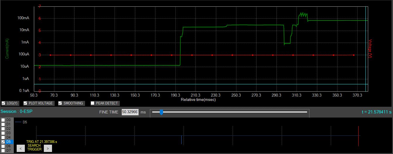
The current profile of an ESP8266 Wi-Fi module is captured here. The module wakes up from sleep using an internal timer and GPIO toggling the RESET pin. The GPIO is captured in the bottom chart. The current rises from 16 μA to few mA in couple of ms. Then it reaches tens of mA and then few hundred mA during the calibration. All of these states are captured in a single range with ZS1100A. This demonstrates the dynamic range, bandwidth, capture length and digital sync feature of the tool. Note how the output voltage remains constant throughout this variation.
| Parameter | Specification | Notes |
|---|---|---|
| Output Voltage Range | 0 to 6 V | Programmable in 10 mV steps |
| Output Voltage Accuracy | Error of 5 mV max | Measured with 500 mA load |
| Current Measurement Range | -0.5 A to 1.5 A (linear range) | |
| Current Measurement Accuracy | 1% of measured value ± 0.2 μA | After one time self calibration |
| Current Measurement Resolution | < 0.1 μA | |
| Max Output Current | 1 A constant current | Vout = 5.0 V |
| 2 A with 10% duty | Measured with 100 ms pulse for every 1 second | |
| Load Regulation | <0.1% | 0 to 1.5 A |
| Measurement Bandwidth | 300 KHz | 3 dB bandwidth |
| Step Response | 2 μS | 10% to 90% of full range |
| Current Sampling Rate | 1 MHz | |
| Sampling Jitter | 10 ps | RMS jitter |
| Voltage Sampling Rate | Once in every 20 ms | |
| Digital Capture | 6 bits at 1 MSPS | |
| Maximum Capture Length | Tested up to 24 hrs | Limited only by the free space on the HDD |
| Programmable Output Resistance | 0 - 10 Ω | In steps of 40 mΩ |
| Error Rate | < 1e-12 | Less than 1 error in 10^12 samples |
| Or less than one sample error in 24 hours |
| ZS1100A | Joulescope™ JS110 | |
|---|---|---|
| Dynamic Range | > 123 dB in single range from 1 uA to 1.5 A | 196 dB with auto ranging |
| Maximum Measurement | 1.5 A | 10 A |
| Resolution | < 100 nA (across the range with avg) | 1.5 nA to 1 mA depending on range |
| Accuracy | 1% ± 200 nA (across full range) | ±0.25% ± 30 nA to ±0.3% ±7 mA depending on the range |
| Sample Rate | 1 MSPS | 2 MSPS |
| Bandwidth | 300 KHz | 250 KHz |
| Response Time | < 2 μs | < 1 μs + Range settling time of up to 5 μs |
| Data Compression | Yes (with option for raw data & different compression strengths) | No |
| Record Size | < 1 GB/hr @ 1 MSPS (saves disk space) | 30 GB/hr @ 2 MSPS |
| Max Record Length | Unlimited (> 24 hrs tested) | Unlimited |
| Uses Range Switching | No (low distorion) | Yes |
| Includes Power Supply? | Yes (0 to 6 V programmable) | No |
| Output Drop | < 1 mV at 1 A | 23 mV at 1 A |
| Programmable output resistance | Yes (0 to 10 Ω) | No |
| Programmable Current Limit | Yes | N/A (only applicable to power supply) |
| Noise Performance | Excellent | Excellent |
| Linearity | Excellent | Great |
| Platform Compatibility | Windows only, Linux, macOS are TBD | Windows, macOS, and Linux |
| Scripting | TBD | Yes |
| Protocol Analysis | Yes (w/ sigrok) | No |
| USB Isolation | Partial (guarantees zero DC ground leakage current) | Yes |
| Thermal Protection | Yes | No |
| Battery Emulation | Yes (most popular batteries used for IoT) | No |
| Open Hardware | Yes | No |
| Open Software | No | Yes |
| NIST Traceability | No | Yes (optional) |
| Cost (US$) | $499 | $799 |
Notes:
Other solutions use range switching, which can cause load tripping or create high noise. The ZS1100A achieves the high dynamic range using precision analog techniques and Digital Signal Processing.
Joulescope is a registered trademark of Jetperch LLC.
We have an online forum at anglercircuits.com where our previous product, ZS2102A, is being discussed. All support, including documentation, user guide, software, drivers, etc. are uploaded here. The same forum shall be used for the ZS1100A. Documentation will also be made available in the project GitHub repository.
The current plan is to manufacture in India or the United States depending on production volume. A low-volume run would occur in India, while a high-volume run would occur in the United States.
All fulfillment and logistics would be handled by Crowd Supply. ZSCircuits will ship the required quantity of products directly to the Crowd Supply warehouse in the USA. All the backers will get their shipments from Crowd Supply directly. You can learn more about the Crowd Supply fulfillment service in this guide: Ordering, Paying, Shipping: The Details.
On the technical side, we do not foresee any risk as the prototype available in the lab meets the required specifications and level of robustness. We have done extensive testing on these samples to get to this level of confidence level. Three Rev2 units have been tested and they match very well, indicating that there is no variation among units.
The main risk lies in the logistics and supply chain disruption brought about by COVID-19. However, the components used in the designed are widely available across multiple distributors. Hence the risk associated with procurement should be minimal, once the supply chains open up.
A few changes will be made in the Rev4 PCB:
All of these changes are verified in simulation and pose no impact to the overall schedule. The Rev4 will be manufactured and fully tested in our lab before the final volume build starts. At least three units will be tested for reliability and stability.
Should any unforeseen issues occur during the final testing and/or production, backers will be notified through project updates.
Produced by ZSCircuits in Bangalore, India.
Sold and shipped by Crowd Supply.

One ZS1100A, along with a power supply, two banana-to-alligator clip cables, eight jumper wires for the front-facing I/O, a USB cable, a flash drive with software, and a quick start guide.

Main area of expertise are Electro-magnetics, RF & Mixed signal board designs, RF test and characterization, Debugging board level problems like spurious emissions, noise coupling analysis, Noise reduction in electronic Systems. In addition we design software and firmware solutions for our products.