Jun 22, 2020
Project update 2 of 14
New Feature - Programmable Output Resistance
by Prajay MadhavanZS1100A power supply output resistance will be programmable, and can be set from 0 to 10 Ω in steps of 0.04 Ω. This is very helpful for real battery emulation. The circuit has already been added to the Rev4 PCB and has been simulated.
Simulation data
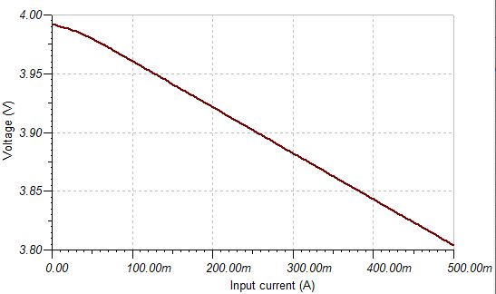
Voltage drop with 0.4 Ω resistor (simulated)
Additional changes between Rev2 and Rev4
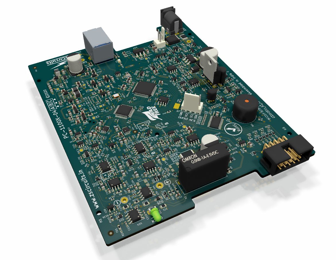
Rev4 PCB
Rev4 is the version that will ship to campaign backers. In addition to the programmable output resistance, the following changes will be made to the Rev4 PCB:
- TO-220 sense resistor will be replaced with high power SMD current sense resistor. The TO-220 part was getting obsolete and other options were non-RoHS.
- Programmable output resistor circuits will be added.
- Blue wiring on the prototype will be fixed.
- Current limiting circuit will be added. Simulated and tested on board by blue-wire.
- RTC will be added on the I²C bus, which can optionally be used to count the warm-up time.
- Over-voltage protection will be added. This is to ensure sudden disconnection of charged inductive loads do not cause a high voltage spike.
- Added protection for high reverse current. This sets a limit of 0.5 A going into the power supply.
All of these changes are verified in simulation and pose no impact to the overall delivery schedule. The Rev4 will be manufactured and fully tested in our lab before the final volume build starts. At least three units will be tested for reliability and stability.