ESP32-M1 Reach Out takes everything you love about the ESP32 module and combines it with everything we know about long-range Wi-Fi communication. There are very few development boards in the high-power Wi-Fi radio market, and nearly all of them max out at 20 dBm transmit power. ESP32-M1 Reach Out is able to transmit at 30 dBm (1 W) conducted, all while drawing power from the USB 3.0 port on your laptop or power bank.
Regulation of ISM-band communication equipment in the United States (under FCC 15.247) allows up to 36 dBm (4 W) of EIRP (Effective Isotropic Radiated Power) for point-to-multipoint links and even higher EIRP for point-to-point links. The 30 dBm (1W) conducted power of ESP32-M1 Reach Out is also permitted in certain European, Asian, South American, and North American countries—as well as in New Zealand. And if you are subject to the limitations put in place by other jurisdictions, you can adjust the board’s transmit power through the ESP32 module or reduce it even further using an on-board RF attenuator.
The Bluetooth and Wi-Fi communication protocols are widely used to connect wireless devices, including access points, computers, mobile phones, and IoT gadgets. The range of existing Wi-Fi boards is quite limited, however—200 to 400 meters at most, given line of sight. As a result, applications for these dev boards are often forced to rely on other protocols to communicate over longer distances. This tends to increase both the size and the cost of end products, as well as the time required to develop them. In some cases, it results in lower data rates as well.
ESP32-M1 Reach Out can increase Wi-Fi range by a factor of two or three while still complying with regulatory requirements, making it perfect for remote monitoring and sensing, drone radios, long-range video streaming, and mesh networking, among other applications. And, if used as a repeater, it can extend the range of such deployments even further!
Our goal is pretty straightforward: to emulate the functionality of other ESP32 boards while giving those boards the gift of extended range. To pull that off, we have carefully designed our own RF front end—from the component level to the system level—and carried out extensive design verification and testing. That meant choosing the right components, putting each of them in precisely the right location, taking advantage of all available board real estate, RF matching, antenna matching, tuning for the power amplifier, PCB trace calculations to account for the dialectric board, and…we could go on. (Filters, low-noise amplifiers, RF switches…) In the end, ESP32-M1 Reach Out was designed entirely by Bison Science engineers, and we think you’ll like it.
This all started when we asked ourselves a simple question: under what circumstances would it be possible to replace mobile data with a network of home Wi-Fi access points? Once again, simple questions tend to have technically complex answers, but the short version is that ten ESP32-M1 Reach Out boards—each able to transmit and receive at a range of 1 km or better—could theoretically provide local connectivity over a 10 km radius.
While this is just the first step toward that particular goal (and we do not yet recommend that you throw away your cell phone), the extended range of ESP32-M1 Reach Out is already useful for many applications.
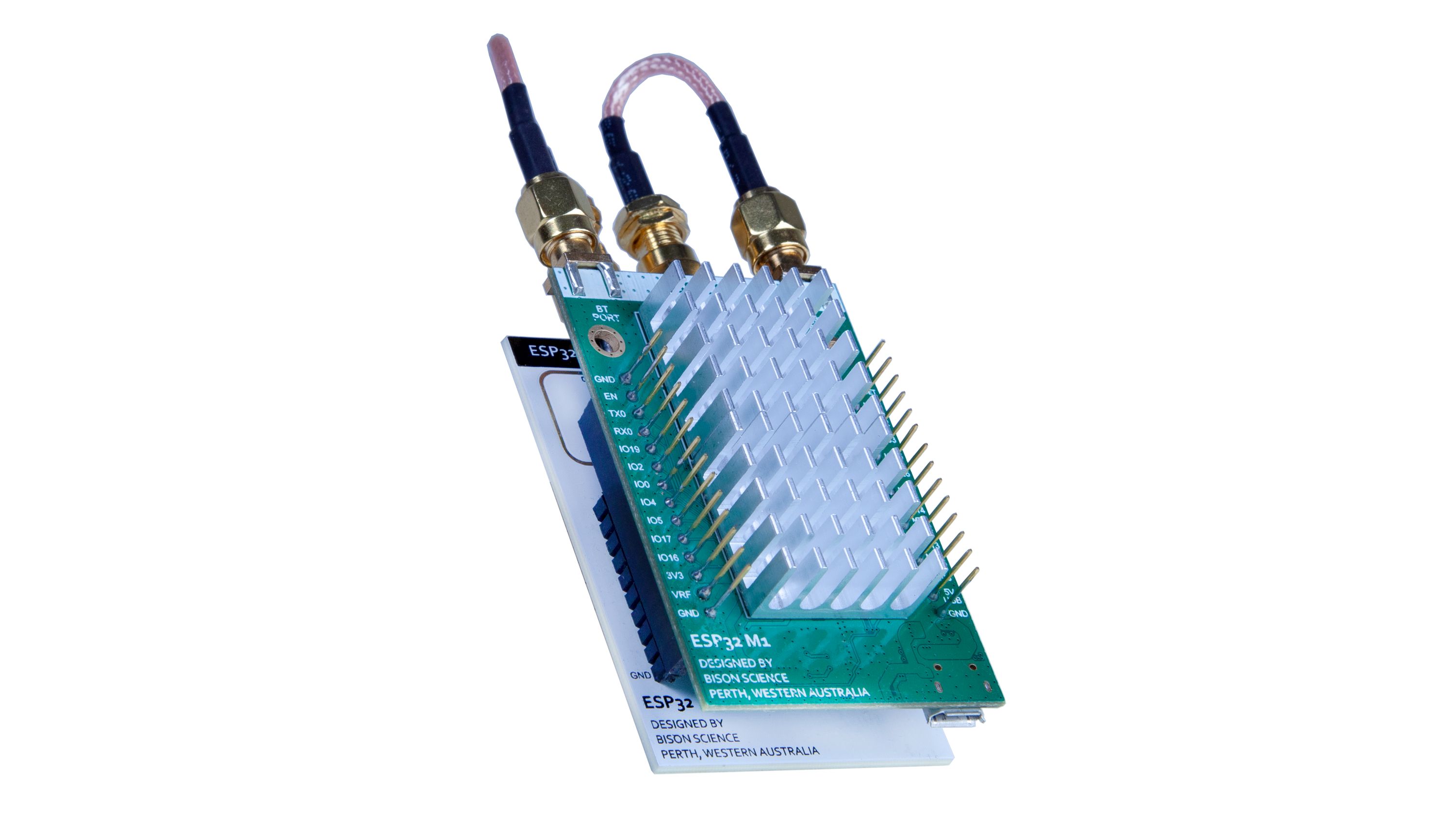
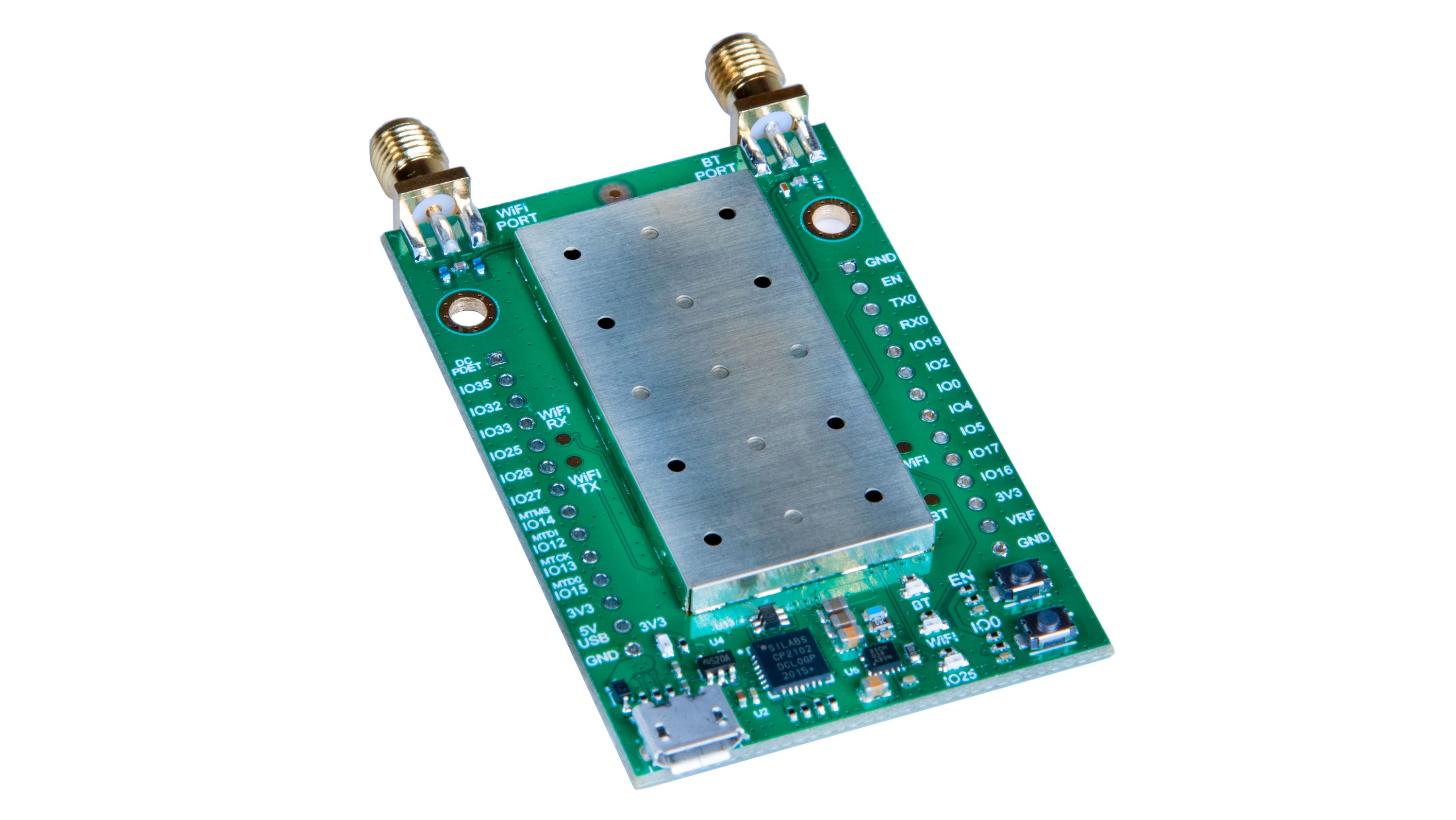
Our core ESP32 dev board provides 18 GPIOs, three different externally-accessible voltage outputs (3V3, 4V9, and USB), a USB bridge, external digital interfaces, external antenna connectors, and a high-power radio front end for Wi-Fi—all in a very compact form factor. The ESP32 module at its core is powered by 3V3 LDO and its RFFE is powered by 4V9 LDO.
The ESP32-M1 Reach Out block diagram is illustrated in Figure 1 below.
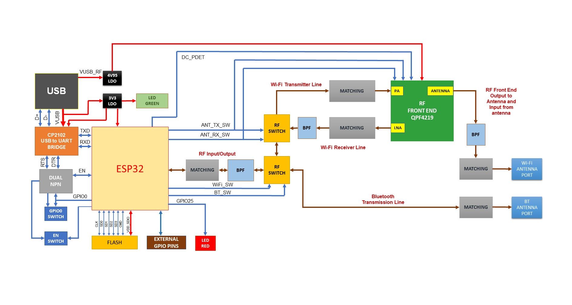
Fig 1: Block diagram of EP32-M1 Reach Out board (click to expand)
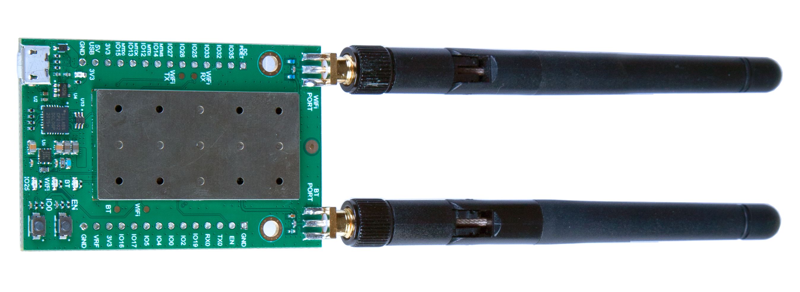
The board itself is illustrated in Figure 2 below. {fig-2-component-placement-on-ep32-m1-reach-out-board | link}
Fig 2: Component placement on EP32-M1 Reach Out board (click to expand)
ESP32-M1 Reach Out involves three major sections: the RFFE, the microcontroller, and the power section.
Our RFFE relies on Qorvo’s QPF4219 module and has a 33 dB transmitter gain and a 15 dB receiver gain at the module level. (The board itself is capable of transmitting from 21 to 30 dBm, though its output power can be adjusted through the ESP32 module at the firmware level.) After input and output matching, the on-board QPF4219 LNA receiver gain is 12 dB. At the input of the ESP32 chip, the receiver sensitivity is 8 dB higher. The bandpass filters, RF switches, and matchings are part of these measurements.
Bandpass filters are placed in three different locations: 1) after the ESP32, to suppress ESP32 PA harmonics; 2) at the output of the QPF4219 antenna pin to suppress the harmonics of the RFFE PA and to pass wanted frequency and reject unwanted frequency in receiver mode; and 3) after the LNA to filter the harmonics of the LNA and to suppress noise in the receiver line up.
The QPF4219 is matched to 50 ohm at the module level. Importantly, the PA, LNA, and antenna ports are all matched to 50 ohm. These optimizations are discussed in more detail below. The ESP32 RF pad impedance is 30+j10, which matches to 50 ohms to provide maximum power transfer.
To avoid user-facing complexity and to maximize compatibility with existing code, we designed the second element of ESP32-M1 Reach Out to emulate the Espressif Dev Kit C wherever possible. We took a similar approach to the CP2102, the USB-to-UART bridge, the buttons (GPIO0 and ENABLE), and the red LED connected to GPIO25.
Power is managed using two different LDOs. For the microcontroller section, including the CP2102, we supply power using 3V3 LDO. The QPF4219 RF front end module is a 5 V device that requires at least a 4V75 power supply, so we had to find a separate LDO for it. To supply the RFFE, we went with a TI ultra-low-dropout TPS7A5201RPST regulator, which we chose after testing many different LDOs in this category and discussing our requirements with TI.
The following are all optimized and matched to obtain maximum power transfer and minimum signal reflection:
The network-analyzer frequency marker is set to 2.4 GHz, 2.45 GHz, and 2.5 GHz for all of the plots shown below. Each section is measured and matched to 50 ohm, as illustrated below.
Figure 3 shows the board setup for RF matching and tuning, and Figure 4 shows the RF Pin 2 from ESP32 matched to more or less 50 ohm.
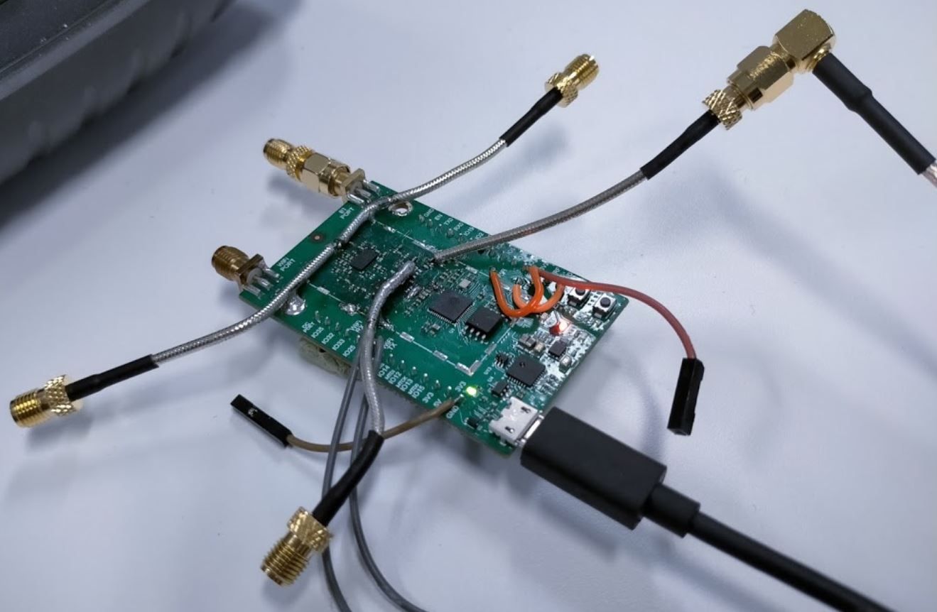
Fig 3: ESP32-M1 setup for multiple optimizations
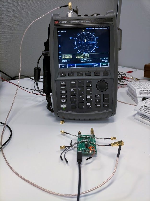
Fig 4: ESP32 chip matched to 50 ohm
Our RFFE PA is optimized and matched for input and output. See Figure 5 for input and Figure 6 for output-matched measurement. The gain measured from the optimized input and output matching is shown in Figure 7. The gain of the PA is approximately 32 dB.
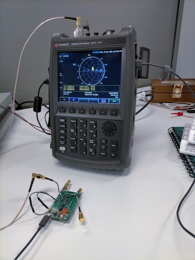
Fig 5: RFFE PA input matched to 50 ohm
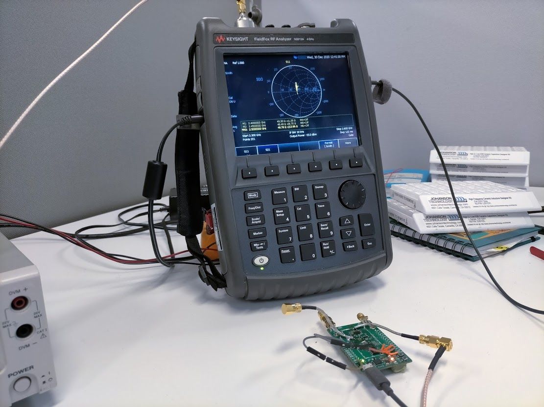
Fig 6: RFFE PA output matched to 50 ohm
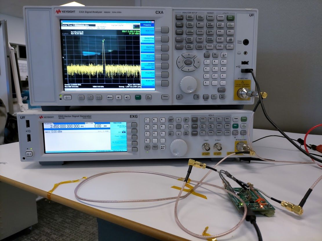
Fig 7: PA gain of the RFFE is approximately 32 dB after input and output of the PA is optimized
The RFFE in receive mode has two configurations: using LNA or using LNA in bypass mode (not using LNA in the receiver line up). By default, the ESP32-M1 Reach Out board uses LNA in the receiver line up. As such, the design of the LNA input is already matched to 50 ohm from the PA output section (see Figure 6). With the transmit and receive lines sharing the same path/pin in RFFE, there is an internal, ESP32-controlled switch to toggle between them. The LNA output is optimized and matched to 50 ohm as shown in Figure 8. The gain measurement in Figure 9 shows the overall receiver-chain measurement, from the Wi-Fi antenna port to the ESP32 module, where the signal is approximately 8dB higher.
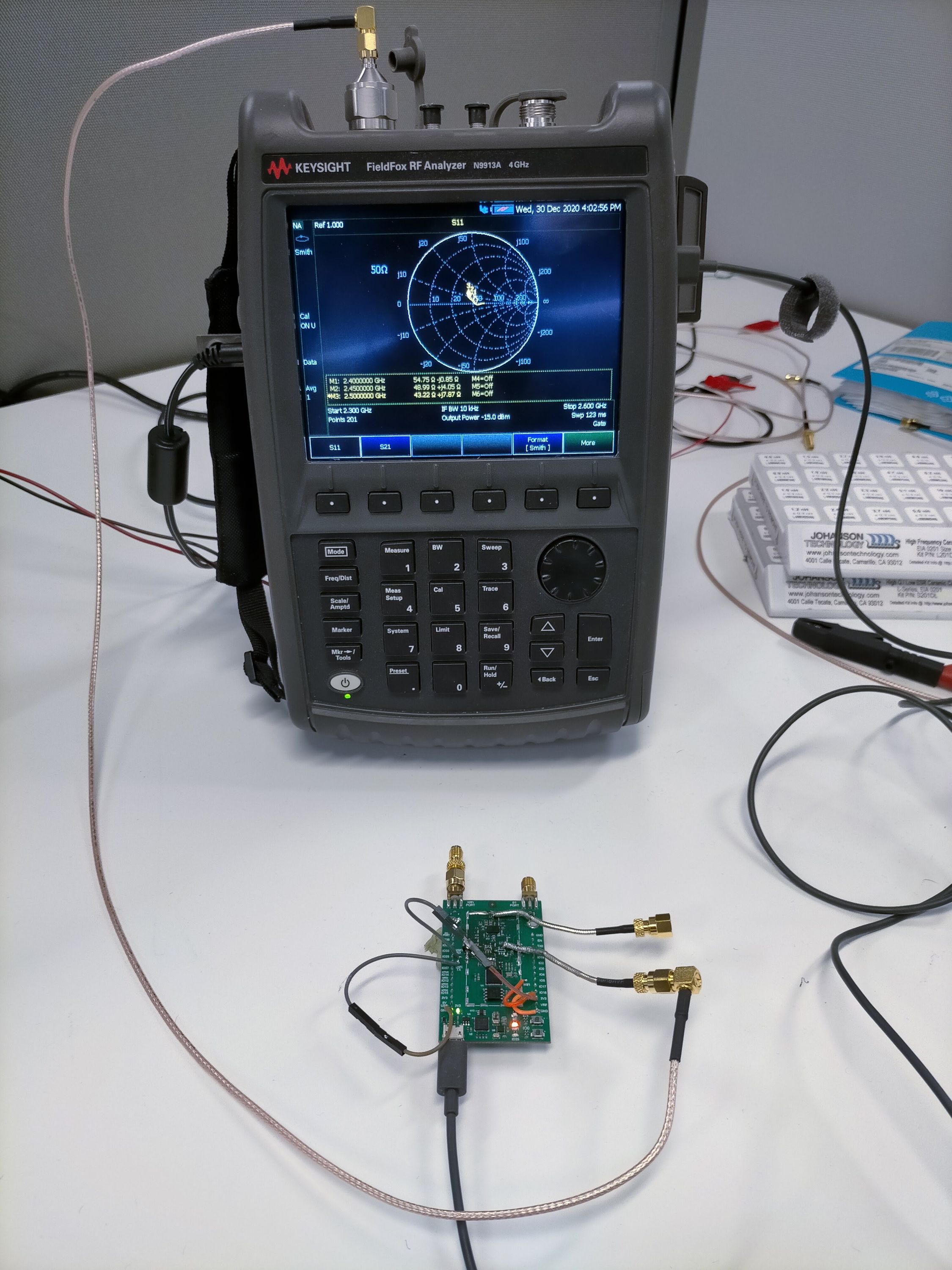
Fig 8: RFFE LNA output matched to 50 ohm
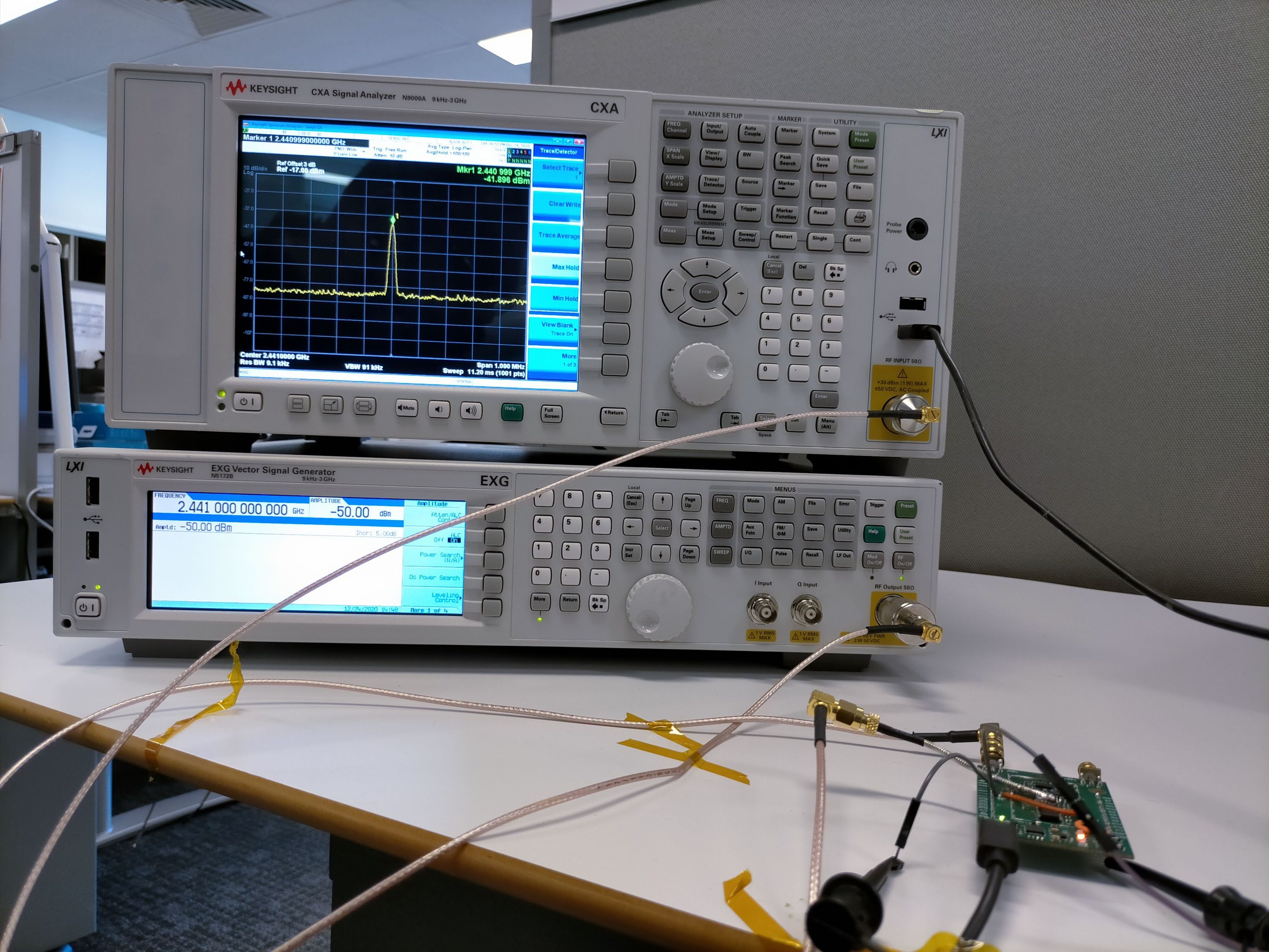
Fig 9: The ESP32 chip receiving 8 dB higher in signal with LNA. At the design stage shown above, the Wi-Fi port is already matched to 50 ohm, as discussed below
The antenna connector port for Wi-Fi and Bluetooth is matched to 50 ohm impedance. This allows 50-ohm antennas to connect directly to both ports. Figures 10 and 11 show this port impedance at 50 ohm after matching.
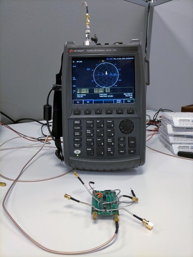
Fig 10: Wi-Fi port matched to 50 ohm
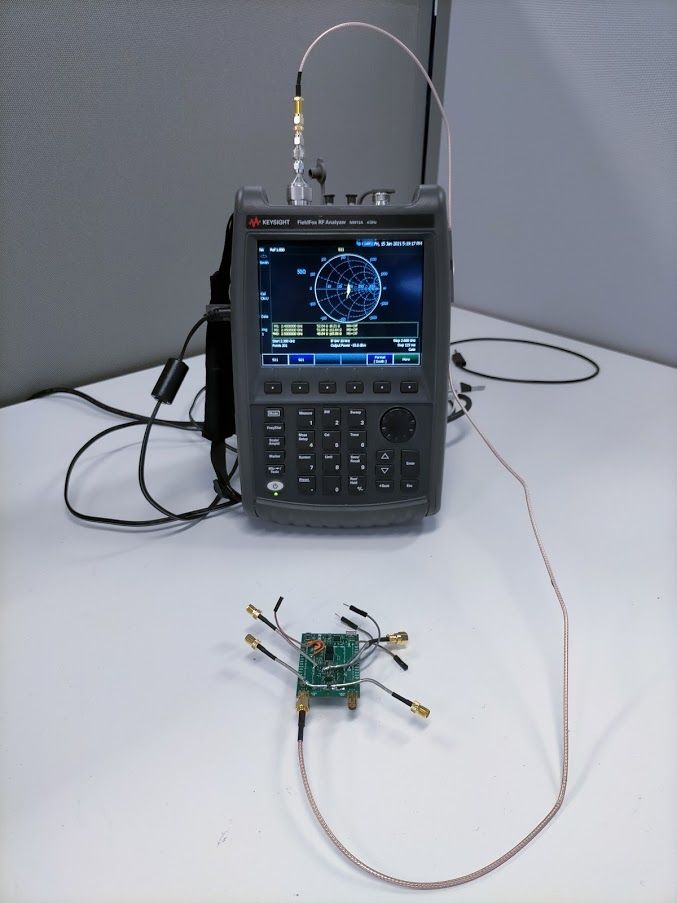
Fig 11: Bluetooth port matched to 50 ohm
The table below compares ESP32-M1 Reach Out to two widely-used ESP32 boards: the Node MCU ESP32S (WROOM-32 module) and the ESP32-DevKitC-32U. As with the other two boards, ESP32-M1 Reach Out followed the design recommendations from Espressif’s datasheets and other supporting documents. The details of the ESP32 module itself are not compared. The technical comparison focused on specific differences relevant to radio performance.
| Parameters | ESP32-M1 Reach Out | Node MCU ESP32S (WROOM-32 Module) | ESP32-DevKitC-32U | |
|---|---|---|---|---|
| Radio | ||||
| Wi-Fi and Bluetooth | Yes | Yes | Yes | |
| RF Front End (Wi-Fi) | Yes | No | No | |
| Output Transmit Power Conducted (Wi-Fi) | 30 dBm | 20 dBm | 20 dBm | |
| Receiver Sensitivity ¹ | -96 dBm | -88 dBm | -88 dBm | |
| External Antenna Ports | 2 (Wi-Fi & Bluetooth) | 0 | 1 | |
| External Antenna Port Type | RPSMA | N/A | U.FL | |
| PCB Antenna | No | Yes | No | |
| Range (Wi-Fi) | 1.5 km ² | 350 m | 700 m | |
| Power | ||||
| Supply Voltage | USB (5 V) | USB (5 V) | USB (5 V) | |
| Output Voltage One | 5 V_USB | 5 V | 5 V | |
| Output Voltage Two | 3.3 V | 3.3 V | 3.3 V | |
| Output Voltage Three | 4.9 V | None | None | |
| Max Current during transmit | ~770 mA ³ | ~250 mA | ~250 mA | |
| Average current during RFFE transmit | ~165 mA | ~90 mA | ~95 mA | |
| GPIO | ||||
| Accessible GPIO | 16 | 22 | 22 | |
| Accessible GPIO Input Only | 2 | 2 | 2 | |
| EN Switch | Yes | Yes | Yes | |
| GPIO0 Switch | Yes | Yes | Yes | |
| LEDs | ||||
| Power Indication | Yes | Yes | Yes | |
| GPIO LED | Yes | Yes | No | |
| Wi-Fi LED | Yes | No | No | |
| Bluetooth LED | Yes | No | No | |
| Physical | ||||
| Weight | 18 g | 11 g | 12 g | |
| Dimensions | 60 x 40 mm | 48 x 25 mm | 48 x 27 mm | |
| Other | ||||
| Sensors | No | No | No | |
| Display | No | No | No | |
| Battery Powered | No | No | No |
¹ Conducted. (Tested with 802.11 b Wi-Fi at 11 Mbps.)
² 1.5 km range was tested on a sunny day with line of sight. At 1.2 km range, test conditions were affected by cars and houses but line of sight was maintained and ranges reached up to 1.5 km. There is no range beyond 1.5 km under these test conditions. No tests were performed at night or on rainy days. Please see the Transmit-Power & Range-Test Demonstration for more details about our test setup.
³ ESP32-M1 Reach Out tested in AP mode transmitting at 27 dBm.
An ESP32-M1 Reach Out board, configured to AP (Access Point) mode, is transmitting at 1 W (30 dBm) conducted. It was set to a low-enough power level that the RFFE was able to perform at 1 W.
With the above settings, one board was configured as an AP and the other as a Station for the range-test video shown below. The setup was as follows:
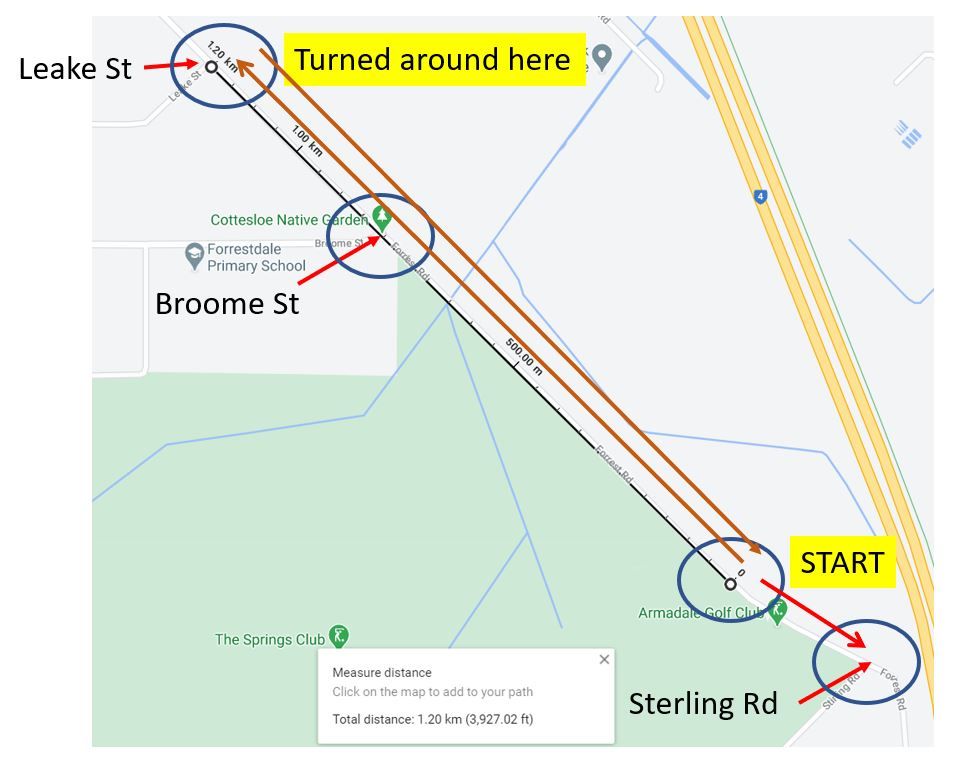
Fig 12: Range test map. The board configured as a Wi-Fi station began near the Armadale Golf Club then made its way to Leake St (approximately 1.2 km) before returning. It then walked in the opposite direction, to Stirling Rd, to provide a reference point. The blue circle is a reference point shown in the video.
ESP32-M1 Reach Out extends Wi-Fi communication range up to 1.2 km (with the potential to reach up to 1.5 km), making it appropriate for applications that need to conduct experiments, collect data, or capture audio and video at remote locations.
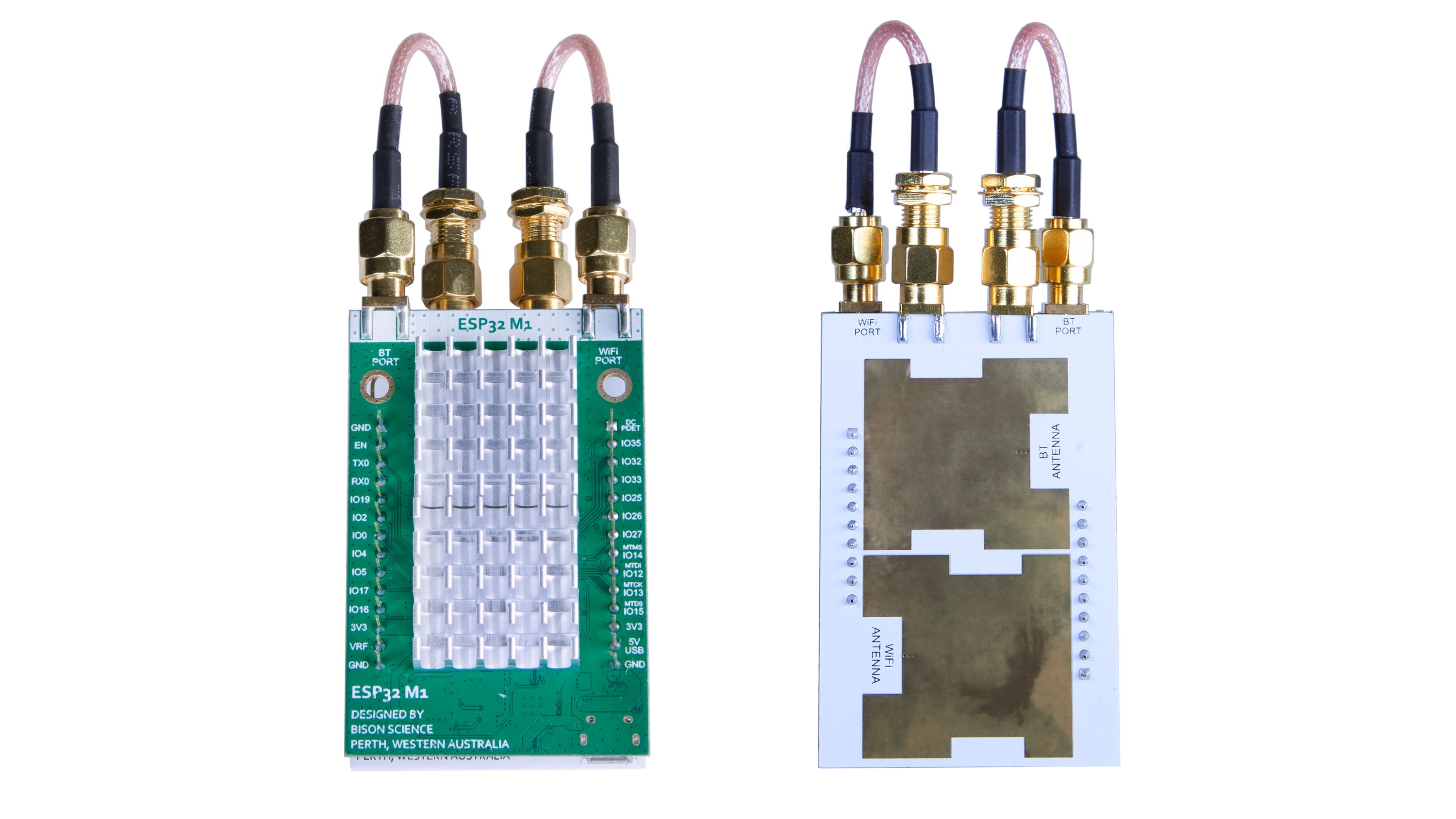
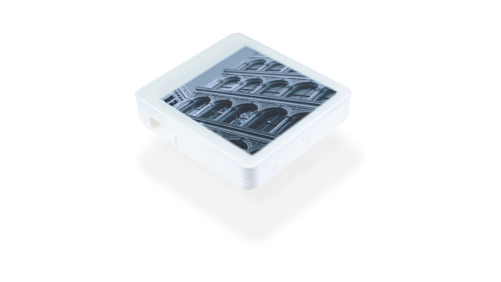
ESP32-A1 is a Roger substrate PCB board with two planar antennas that mounts directly on the ESP32-M1 Reach Out board and occupies both of its antenna ports. This design attempts to help address the issues that arise when a radio device with a traditional antenna is placed against a material that reduces the gain of that antenna or the material that acts as a ground plane. Examples might include radios that are placed against a concrete wall or ceiling, mounted to a metal surface, placed flat on the ground, or held against a body.
We designed the ESP32-A1 antenna to meet the following requirements:
Based on the above design requirement, a suitable candidate would be a Microstrip Patch Antenna (MPA). Unfortunately, a typical 2.4 GHz radiating patch dimension is approximately 40 mm x 35 mm—not including the feed—which is too large to place two antennas on a 60 mm x 40 mm host board.
Taking on the challenge described above, we started with a simple square patch, on an FR-4 substrate. The thickness was fixed to 1.6 mm for ease-of-manufacturing and to keep the antenna further from the ground plane. We designed a single patch and simulated its use—resonating at 2.45 GHz—with a 3D antenna simulation tool. We initially used the inset feed method but this made the MPA dimensions too large.
Optimizing further, we switched from an inset feed to a via feeding on the bottom of the PCB. This is similar to a coaxial feed but the SMA connector is kept at the edge of the board, which allowed for a long microstrip line between the ground plane on the bottom layer. (MPAs need a solid ground under the patch for good gain.) With the feeding method worked out and room for two adjacent antennas, we set to work. After many design changes and optimization, we finally obtained the correct resonance and gain.
Unfortunately, the gain of two MPAs on a small FR4 PCB was not promising, so we opted for a better antenna substrate: Roger RO4350. Given the same thickness, we ended up with a slightly larger patch, but everything still fit within our maximum PCB size.
See Figures 13 and 14 for the assembled antennas. Resonance was shifted to a slightly higher frequency, so we matched the antenna and got it resonating at the intended frequency. The S11 measured impedance is shown below in Figure 15 (for Wi-Fi) and Figure 16 (for Bluetooth). MPA gain was measured in an anechoic chamber and the gain pattern at 2.45 GHz is shown in Figure 17 (approximately 2.7 dBi and 55% efficiency for Wi-Fi) and Figure 18 (approximately 0.7 dBi and 44% efficiency for Bluetooth).
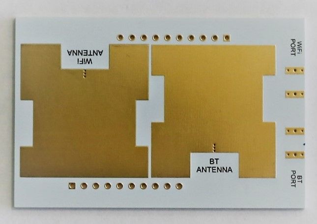
Fig 13: ESP32-A1 antenna board front shows antenna for Wi-Fi and Bluetooth
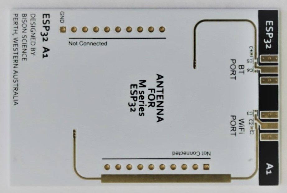
Fig 14: ESP32-A1 antenna board back shows antennas feed
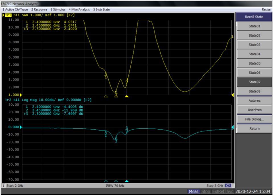
Fig 15: ESP32-A1 Wi-Fi S11 measurement (click to expand)
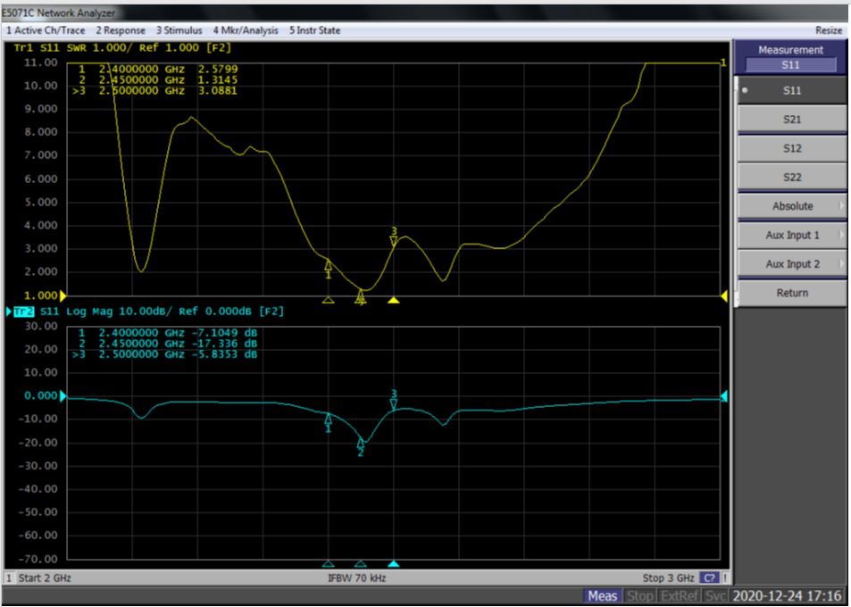
Fig 16: ESP32-A1 Bluetooth S11 measurement (click to expand)
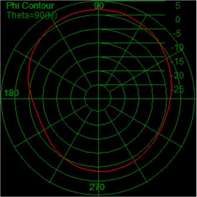
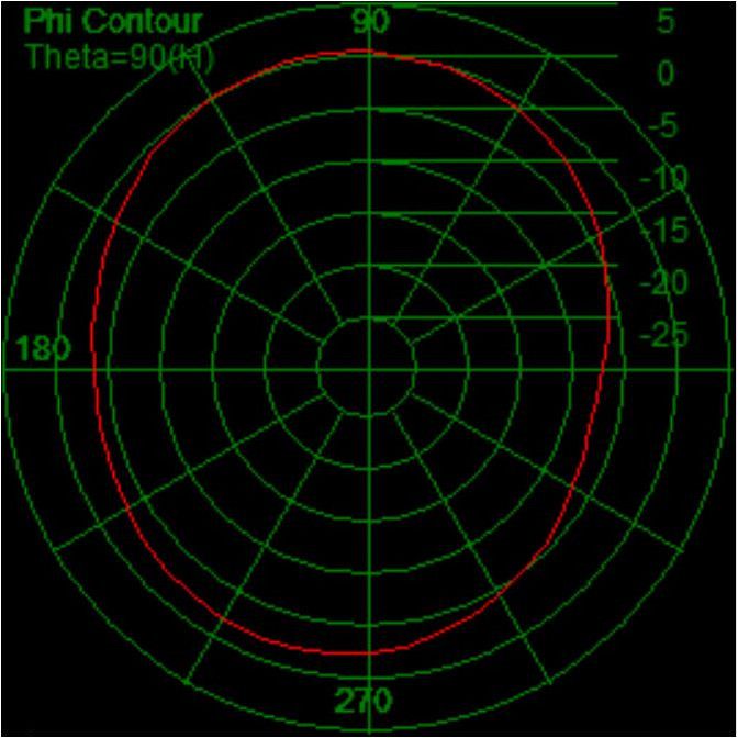
Fig 17: ESP32-A1 Wi-Fi (left) and Bluetooth (right) 2D-radiation patterns at 2.45 GHz
The ESP32-M1 Reach Out board schematics and design files are on our GitHub repository. You can also find us on Facebook and Instagram. And finally, if you have any questions at all, please feel free to reach out using the Ask a technical question link on our campaign page.
The Bison Science team has twenty plus years of engineering experience, ranging from initial concept studies to product design and development to manufacturing and testing. Our engineers handled every aspect of ESP32-M1 Reach Out development: board design, component real estate analysis, part selection and placement, RF-design, shield design, and Design for Manufacturing (DfM) review.
Our PCBs will be manufactured in China and shipped to the Bison Science offices for in-house testing, as we have the specialized RF-testing equipment (and the exacting standards) necessary to ensure that the final product we ship to backers is of exceptional quality.
After testing and packaging the first batch of ESP32-M1 Reach Out boards, we will send them on to Crowd Supply’s fulfillment partner, Mouser Electronics, who will distribute them to backers. You can learn more about Crowd Supply’s fulfillment service under Ordering, Paying, and Shipping in their guide. Unfortunately, we are unable to ship ESP32-M1 Reach Out to European backers, as it is not CE marked.
Our team is very much looking forward to shipping your boards! While the global pandemic may impact our sourcing, manufacturing, and shipping schedules, we are doing everything in our power to mitigate these risks, and we will be sure to keep you informed as we make our way through the manufacturing process.
ESP32-M1 Reach Out is part of Qorvo RF Accelerator
QPF4219TR13-5K
· RF front end
enables RF range
RFSW8009TR7
· RF switch
enables RF range
Produced by Bison Science in Perth, Western Australia..
Sold and shipped by Crowd Supply.

A long-range, small-form-factor, USB-powered ESP32 Wi-Fi transceiver board with a 1 W (30 dBm) RFFE module. Provides external antenna connectors for Wi-Fi and Bluetooth, GPIOs, and support three different output voltages.

A low-profile, planar antenna with an RPSMA connector. (1 dBi gain for BT and 2.5 dBi gain for Wi-Fi.) Able to fit on top of ESP32-M1 Reach Out for 2.4 GHz to 2.5 GHz applications.

Bison Science based in Perth, Western Australia a hardware tech house designing communication and electronic products to reach global tech communities. Bold, affordable, open source platforms engineered for usefulness and high quality.