Project update 7 of 7
Production Complete & SenseTemp Auto Calibration
I’m pleased to announce that all Crowd Supply campaign orders shipped out at the end of April.
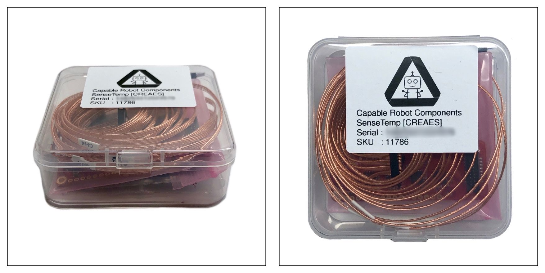
One small change to the shipments is that SenseTemp Kits, SenseTemp TEC Kits, and standalone RTD Harnesses shipped in translucent plastic boxes, pictured above. These cases work wonderfully to store and protect the RTD Harness, which can become tangled and is somewhat difficult to slide into a bag.
Since that shipment, we’ve been wrapping up testing of an additional batch of boards that will be stocked at Crowd Supply in the coming weeks.
Having access to this larger batch of hardware has allowed some exciting measurement and testing to occur across a larger sample size, and resulted in the development of an auto-calibration process for SenseTemp.
Production Testing Summary
As part of the production testing process, each SenseTemp board is plugged into an RTD Harness, which is thermally coupled to a large aluminum block via a compliant thermal pad and light pressure. In an ideal world, this would mean that the attached SenseTemp measures identical temperatures on all four channels.
Unfortunately, there are production tolerances throughout the measurement chain:
- The RTD itself is rated to ±0.15 C
- The MAX31865 has a tolerance of 0.013% (in Kelvin) or 0.038 C at 20 C ambient.
- The 4.3 kohm reference resistor has a tolerance of 0.05% (in Kelvin) or 0.147 C at 20 C ambient.
Testing of 40 units looks like this:
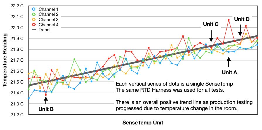
You might notice an overall positive trend in this graph. That is because the ambient temperature in the room changed slightly as production testing progressed. A linear trend line was fit to the data, but this isn’t an ideal ground truth as the ambient temperature rate of change decreases near the end of the test period and measurement outliers effect it too.
You can get a clearer picture when you separate each channel and include the 0.185 C error bars on each measurement (the sum of MAX31865 and reference resistor error)
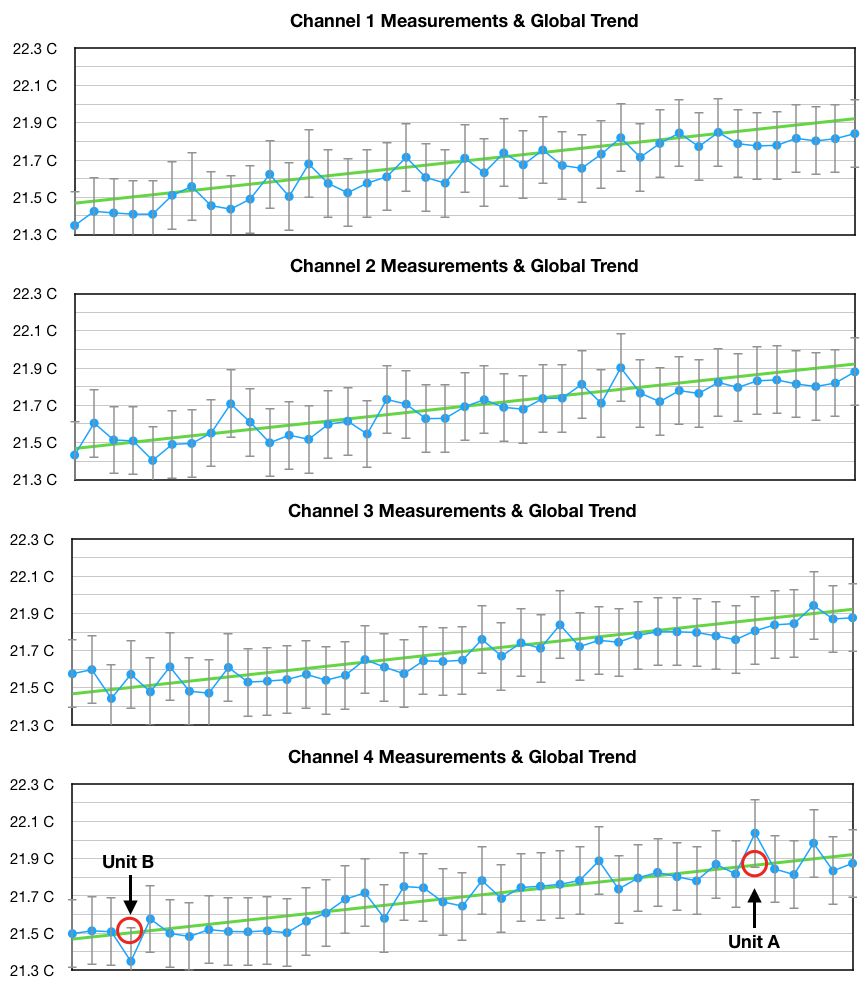
Here, you see that the most significant positive and negative outliers between any single measurement and the global trend both occurred on Channel 4 of different SenseTemp units. These two units, named here A and B will be used later for auto-calibration testing — along with two units (C & D) that had very low measurement variance.
Although there are outliers seen here, it is encouraging to see that all SenseTemps were within their specified ±0.185C tolerance.
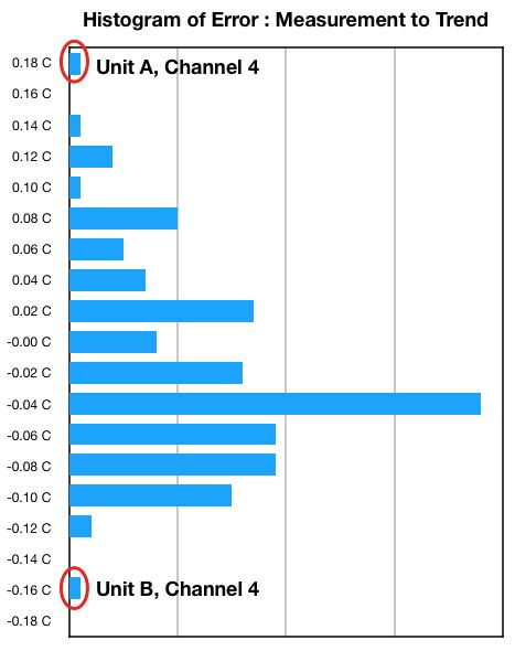
Interestingly, the error distribution is not symmetric about the trend line; there are more measurements below the trend than above. This could be due to the trend line itself not being correct, or a reflection of non-symmetry in the 0.05% reference resistors.
Auto Calibration
One possibility when you have multiple measurements of a single physical property is to use the difference between measurements (the error) to reduce the error. You have to be careful when you attempt this as correctly identify the "good" and "bad" readings; otherwise, you might pull or bias good data toward bad data.
The auto-calibration process developed for SenseTemp is best understood by looking at the code on GitHub, but the process flow diagram is reasonably clear too.
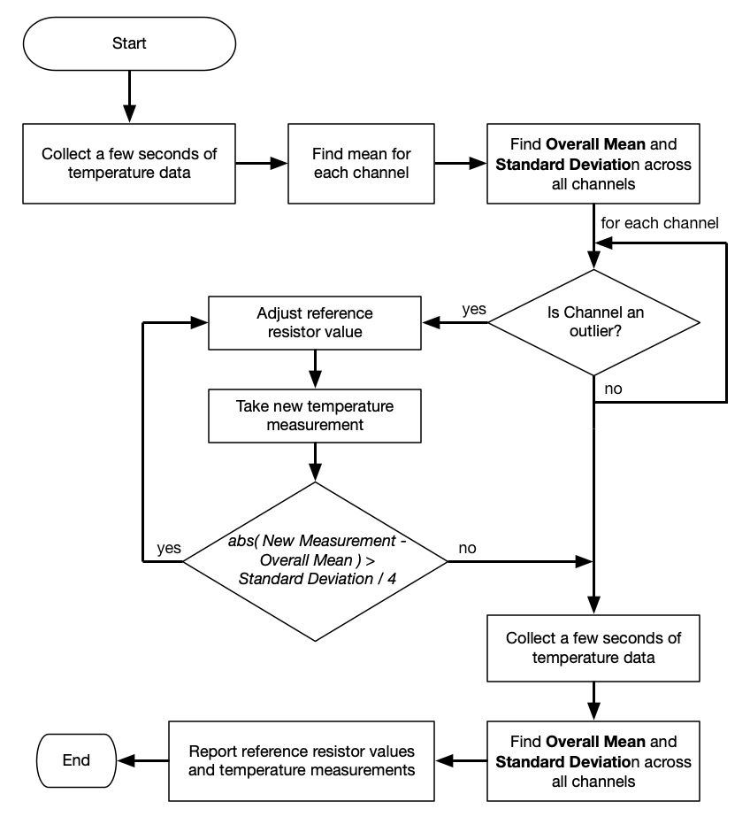
When executed within the CircuitPython REPL, the process looks like this:
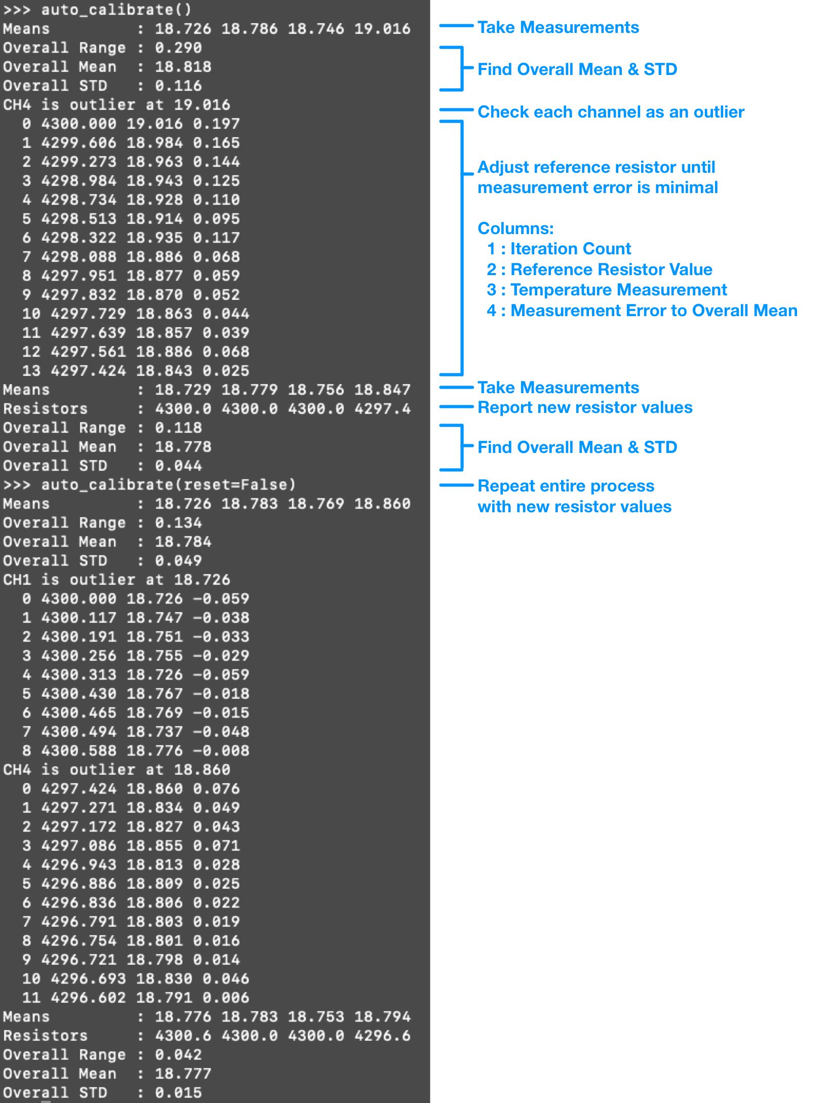
In this instance, the first running of auto-calibration identified Channel 4 as an outlier and adjusted its reference resistor value to 4.2974 kohms. This reduced measurement bounds on the four channels from 0.290 C to 0.118 C.
A second running of the calibration, using the new Channel 4 reference resistor value, found that Channels 1 and 4 were outliers. Changing their resistor values to 4.3006 and 4.2966 kohms respectively reduced temperature variance between the channels to 0.042 C.
As I mentioned, a danger in this kind of self-calibration is moving good data toward bad data instead of the other way around. This seemed to be avoided here by correctly identifying outliers and only adjusting those channels instead of all channels at once.
The other dangers of self-calibration are:
- The system being under-damped and shooting past the ideal calibration.
- The system converging on an incorrect solution (different than other units would). This is similar to the "good toward bad" problem mentioned above, but harder to recover from in the case that all sensors are biased in a particular direction.
To visualize convergence, four SenseTemps were auto-calibrated four times, which each calibration starting from the results of the previous calibration. Two of these (A & B) were selected from the population due to large outliers they had and the other two (C & D) had low variance during initial testing.
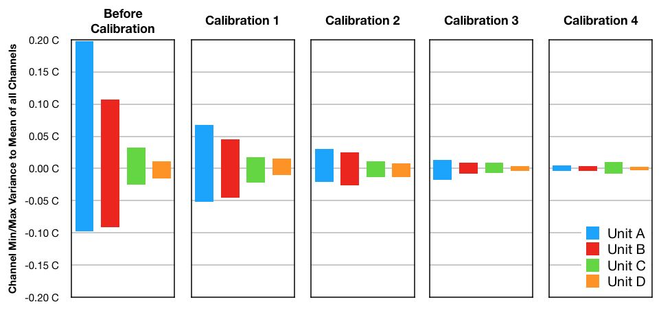
From iteration to iteration you can see that variance between channels (measured here at max - mean and min - mean) either reduced or were constant when subsequent calibrations were run. Unit C did not converge as tightly as the other three but was still reduced by a factor of 3 from its initial uncalibrated state.
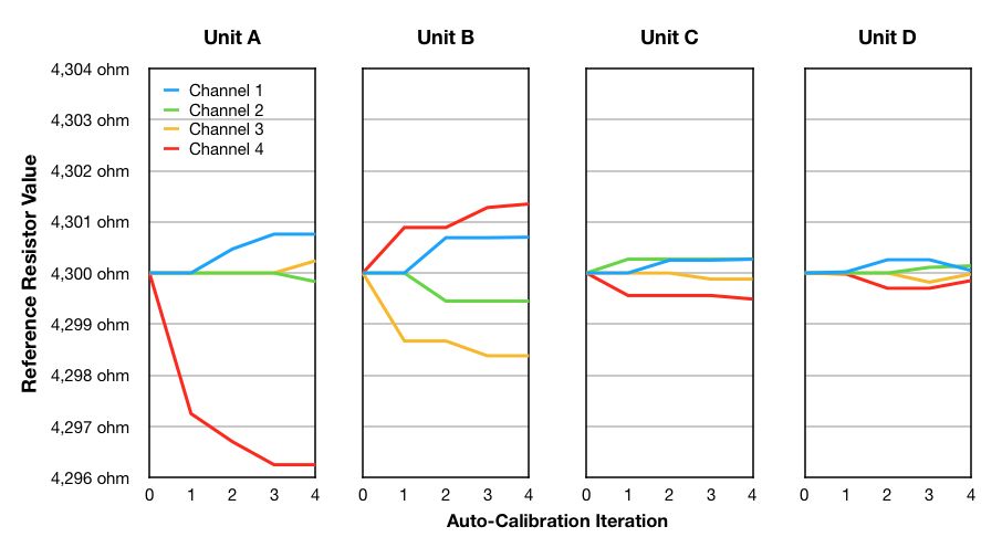
When looking at the adjustment to reference resistor values, you can see the convergent behavior of the auto-calibration process. The most significant changes happen at iteration 1, and subsequent iterations show smaller adjustments. This iterative approach prevents the process from over-shooting the ideal resistor value.
Lastly, we must consider the unit to unit variance and error. It appears the calibration converges well to reduce variation, but do SenseTemp units converge toward a common understanding of temperature? To analyze that, we must look at actual temperature measurements, not relative error to other channels.
These four SenseTemp units were auto-calibrated on in quick succession (to minimize effects of ambient temperature change on the reference metal), and these are the results:
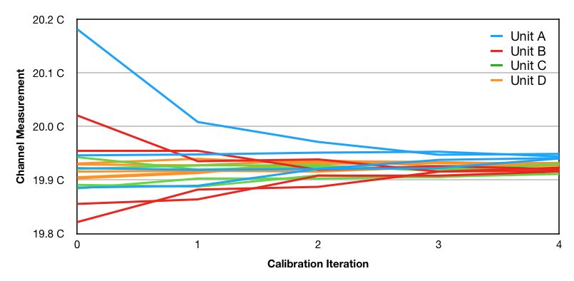
| SenseTemp | Initial Max | Initial Min | Initial Range | Final Max | Final Min | Final Range | |
|---|---|---|---|---|---|---|---|
| Unit A | 20.181 C | 19.886 C | 0.296 C | 19.949 C | 19.940 C | 0.009 C | |
| Unit B | 20.021 C | 19.821 C | 0.199 C | 19.923 C | 19.916 C | 0.007 C | |
| Unit C | 19.943 C | 19.884 C | 0.058 C | 19.930 C | 19.911 C | 0.019 C | |
| Unit D | 19.931 C | 19.904 C | 0.027 C | 19.932 C | 19.927 C | 0.005 C | |
| Overall | 20.181 C | 19.821 C | 0.360 C | 19.949 C | 19.911 C | 0.038 C |
Auto-calibration reduced variance between these 16 temperature channels from 0.36 C (50% of SenseTemp’s specified error limits) to 0.038 C (6% of SenseTemp’s specified error limits).
Note that this is total system error — it includes the error in the RTD sensing elements, MAX31865 chips, and reference resistors. The process here cannot delineate between RTD error and reference resistor error, so if you change the RTD harness used with your SenseTemp you should either remove the auto-calibration reference resistors settings or redo the auto-calibration.