Project update 4 of 7
SenseTemp TEC Thermal Chamber
First, thanks to everyone who’s purchased a SenseTemp or SenseTemp TEC! This campaign is a few days from over, and the final update before the campaign closes is a rather large one.
In this update, I’ll show how you can convert a Peltier-based incubator or fridge into an instrumented thermal test chamber with SenseTemp TEC. These instructions are also very relevant if you want to build your own chamber with the SenseTemp TEC Module or your own Peltier Cooler.
WARNING
To start, a warning: embarking on this sort of retrofit requires knowledge of how to handle power tools and AC mains voltages.
Do not attempt unless you understand the dangers involved and are willing to void the warranty of your Peltier-based incubator or fridge.
Capable Robot Components is not responsible for any property damage or personal injury which results from following these instructions, incorrect usage, or inaccuracies in this guide. PROCEED AT YOUR OWN RISK.
Adding a cable pass-thru
When testing embedded electronics, it’s very useful to have power and communication cables to your device under test inside of the test chamber, in addition to the SenseTemp RTD leads. Adding a pluggable cable pass-thru to the side of your chamber allows you to easily feed these cables into the chamber and maintain connections while the front door is closed and the chamber running.
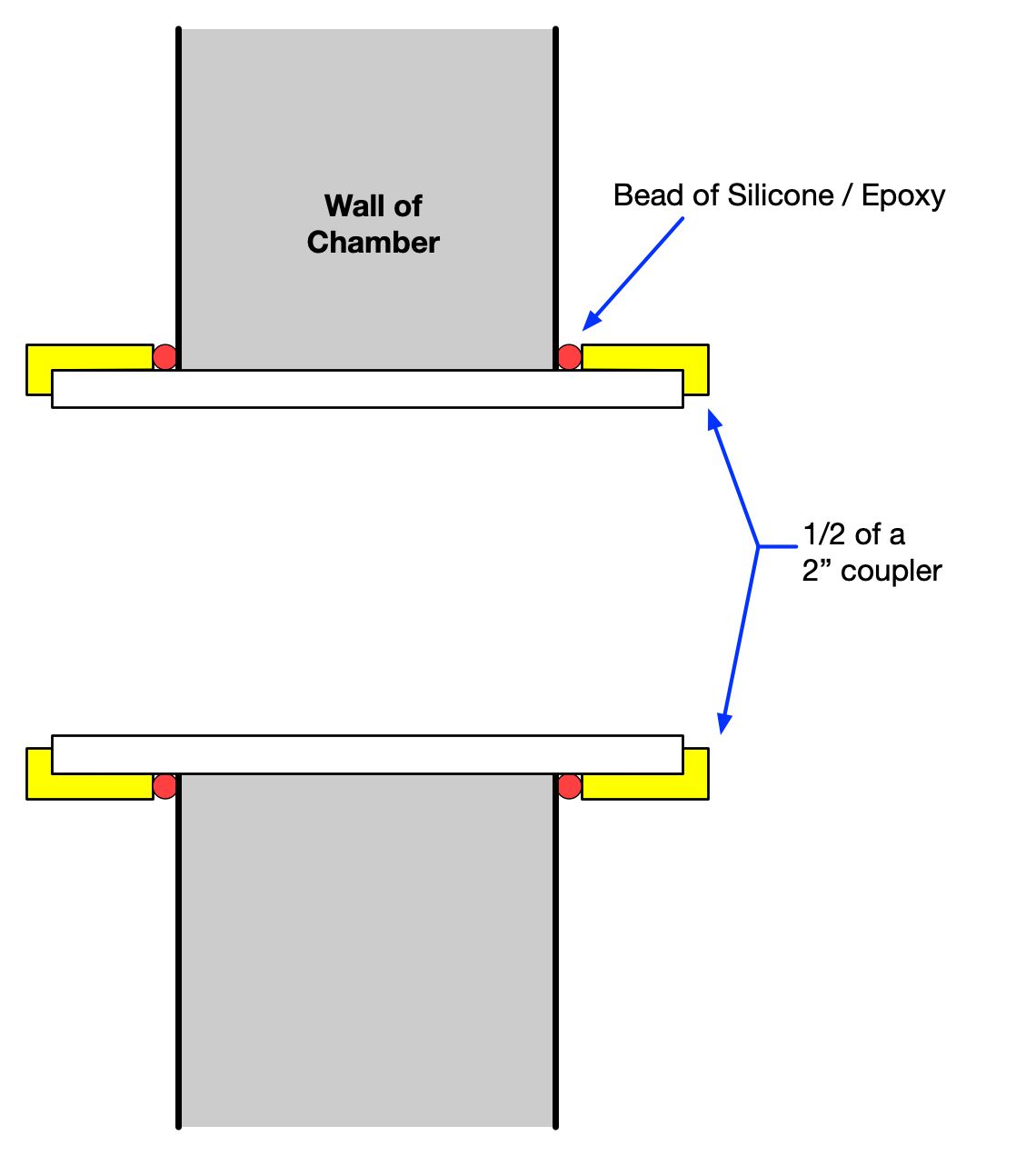
Here, a short section of 2" PVC with a 2" PVC coupler cut in half is used to create the pass thru, and a bit of epoxy was used to seal the tube to the inside and outside wall of the chamber.
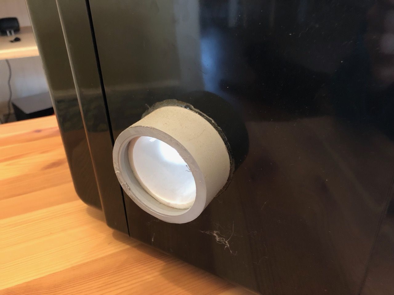
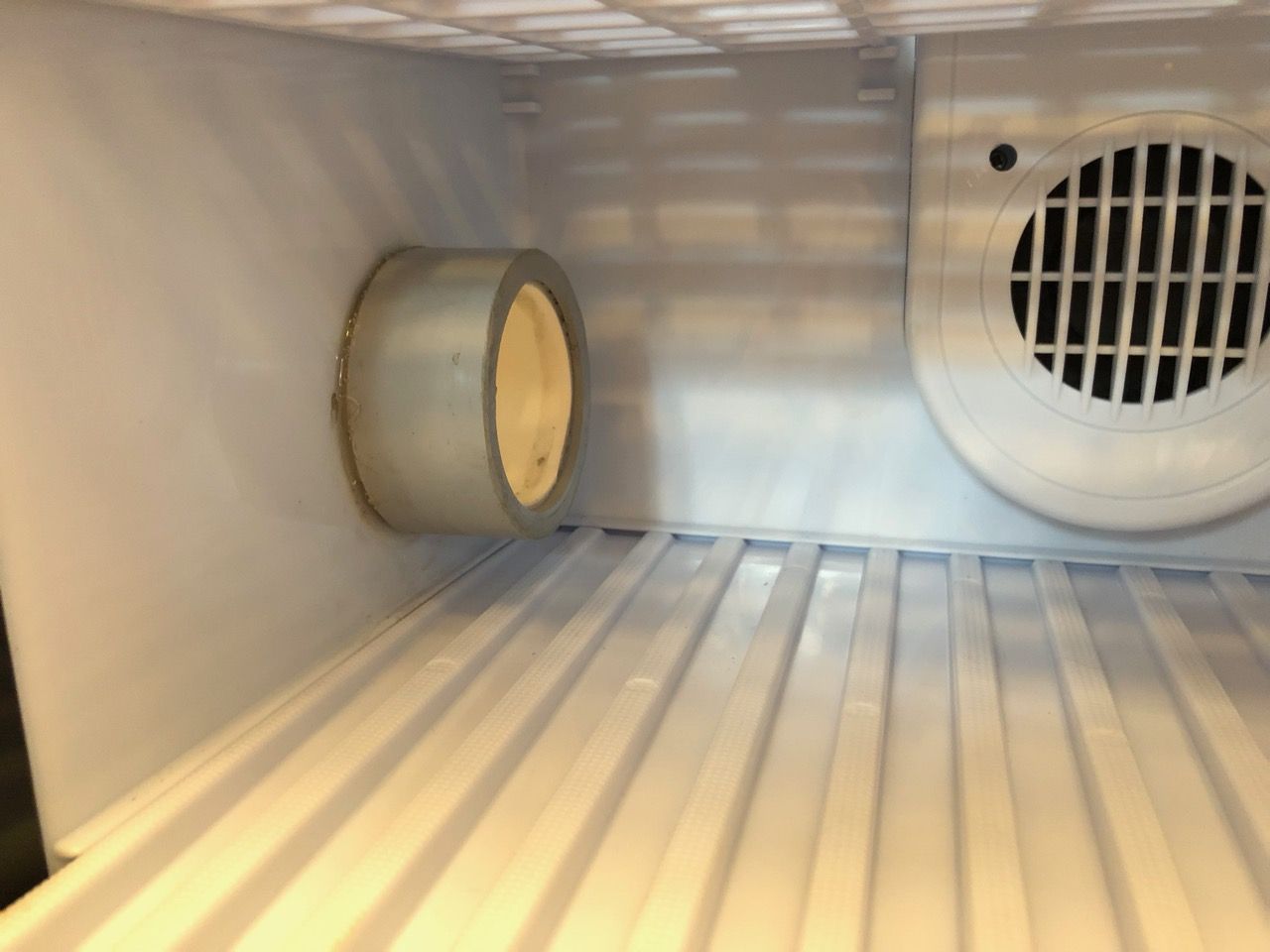
This diagram may help you visualize how these various pieces fit together to form the pass thru.
Once the cable pass-thru has been added to your chamber, you can wire and install the SenseTemp TEC.
Installing SenseTemp TEC
The end result of the wiring and installation of SenseTemp TEC will allow it to power and control interior / exterior fans and the Peltier element itself.
The interior fan will stir and mix the interior air, keeping the temperature within the chamber uniform. The exterior fan cools the waste heat side of the Peltier element by convective cooling to the ambient environment.
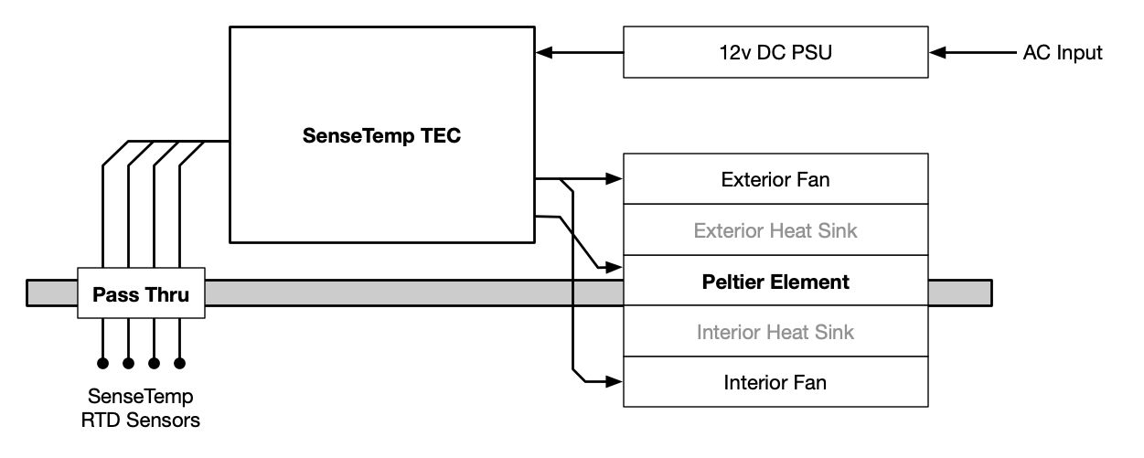
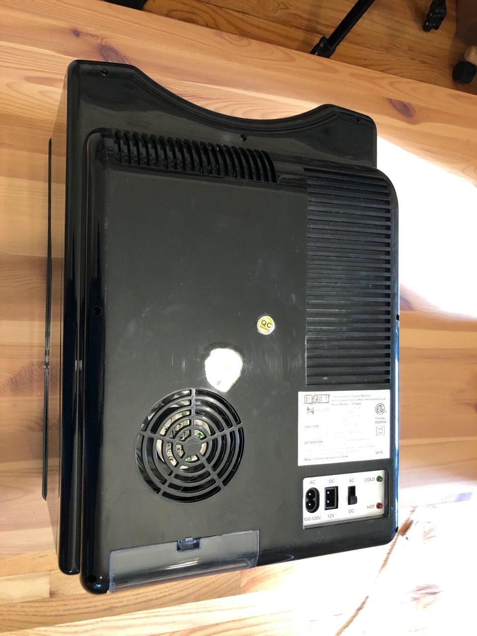
First, open up the back side of your chamber and locate the components you’ll be connecting too.
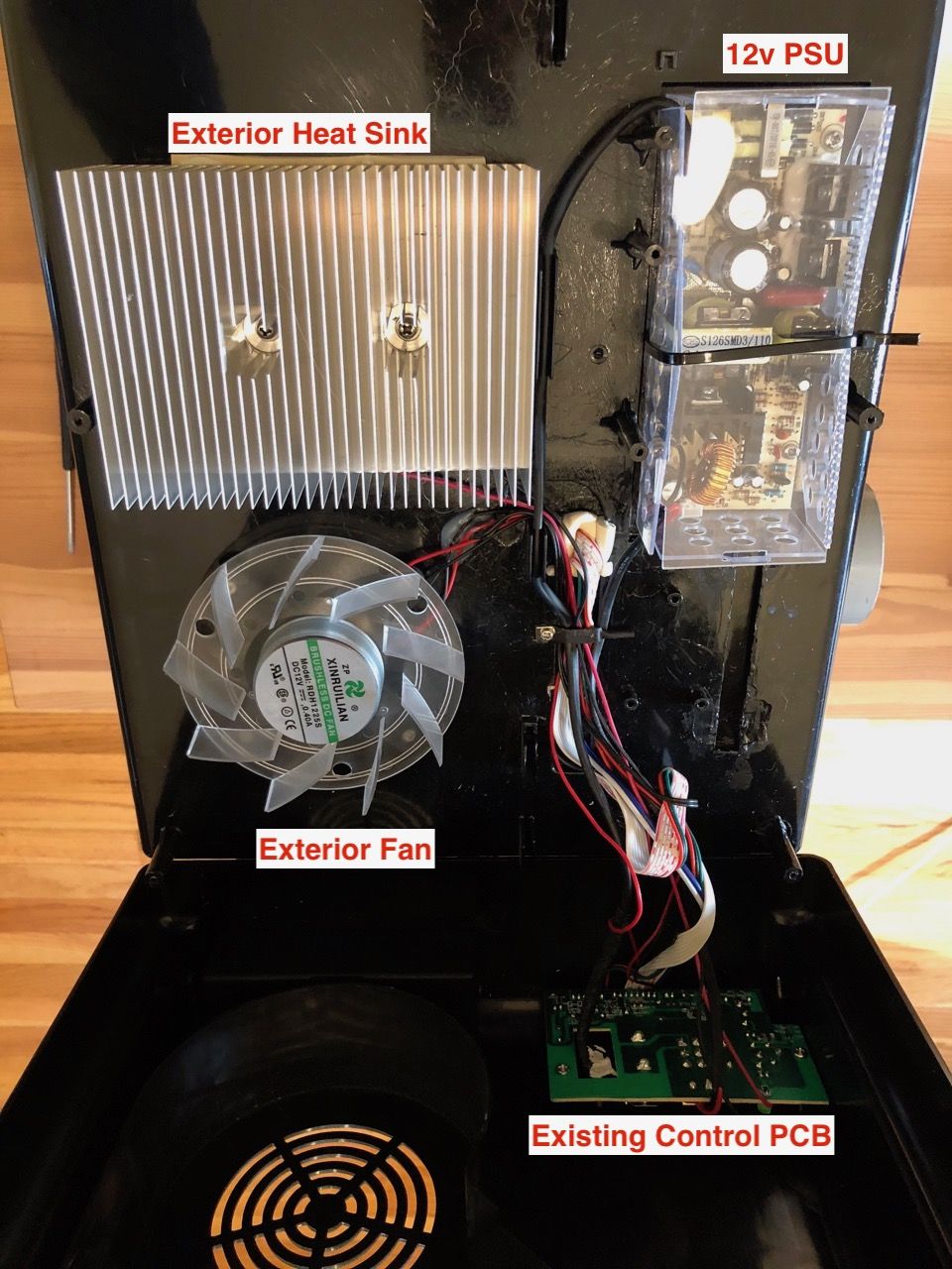
Clip the wires leading to the fans, Peltier element, and from the 12 V PSU as close to the control PCB, to leave useable lengths on all of these. NOTE: do NOT clip the AC mains wires which run from the control PCB to the 12 V PSU — in this chamber, they enter the PSU at the top and the wires are blue & brown. We want to maintain the AC input connection to the PSU.
Then terminate the leads with Molex Micro-Fit connectors, or solder the pre-terminated wires which came with your SenseTemp TEC kit to the lead.
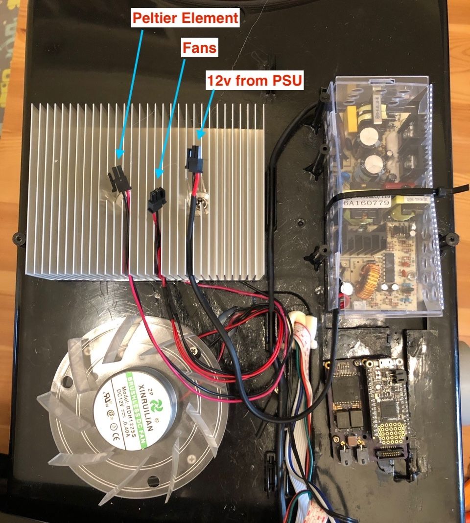
This prototype version of the SenseTemp TEC does not have fan control, so they are terminated into 2 pin header and plugged into the 12 V rail via a Y cable. Production SenseTemp TEC boards have a 4 pin Molex connector which allows fans and the Peltier element to be directly powered by the SenseTemp TEC.
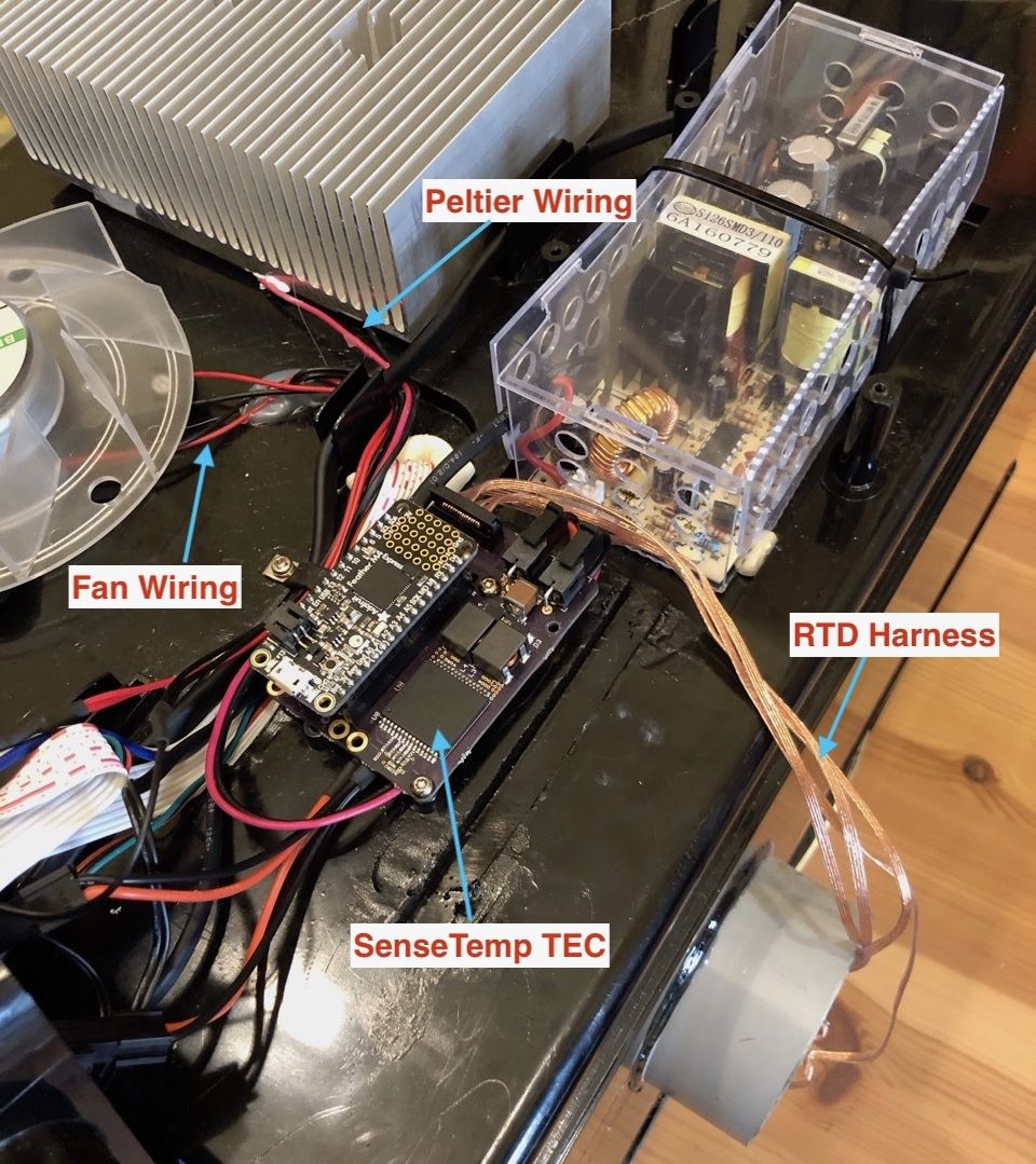
This chamber has a few plastic posts beneath the 12 V PSU which line up with the Adafruit Feather holes in the SenseTemp TEC. Two screws are used to install the SenseTemp TEC on these posts.
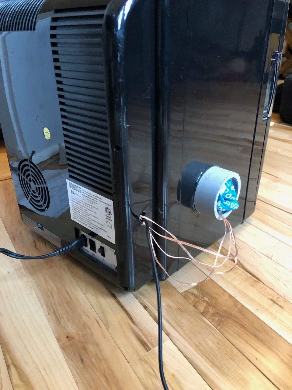
After drilling a small hole in the rear cover, run a USB cable and RTD harness leads thru it. The RTD leads then enter the chamber thru the previously install pass-thru. The USB cable can connect to a computer or Raspberry PI to get temperature data from the RTDs and control chamber behavior.
Run Your Chamber
Now you can design and run different temperature profiles for your chamber. Here, a simple cooling -> heating profile was run. Steps:
- 10 minutes: 50% cooling
- 10 minutes: 100% cooling
- 1 minute: Idle
- 10 minutes: 50% heating
- 10 minutes: 100% heating
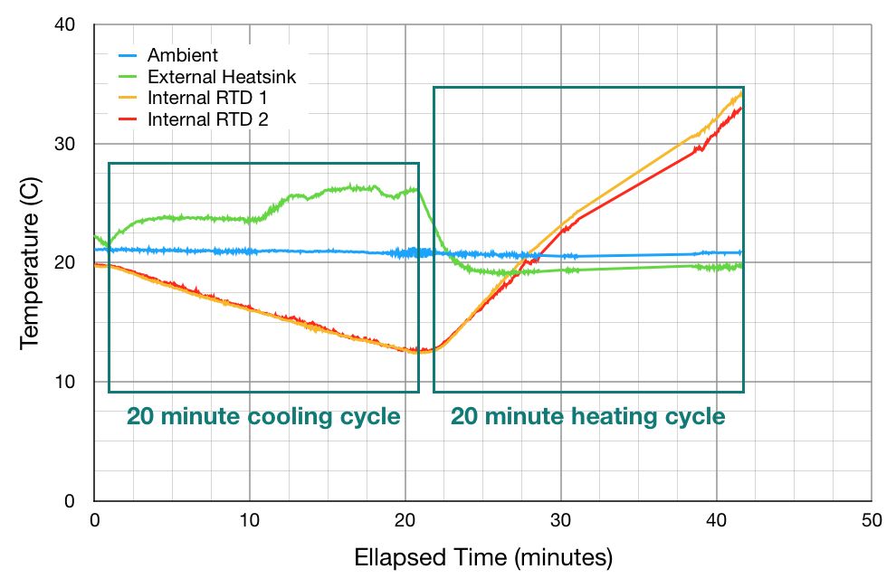
The cooling rate for this chamber is about 0.4C per minute (20 C to 12 C in 20 minutes) and the heating rate is about 1 C per minute (13 C to 33 C in 20 minutes).
You may notice that the cooling rate did not change when the duty cycle on the Peltier changed from 50% to 100%, but it did generate more waste heat (observable in the step change in the exterior heat sink temperature). The efficiency of Peltier elements decreases as you increase the voltage across them. Higher voltages do pump more heat thru the element but generate much more waste heat. This increases the temperature of the element (if the exterior heat sink is a cooling bottleneck) and reduces its’ pumping capacity.
This graph is also a great visualization of what Peltier elements do - they pump heat. When removing heat from the chamber, the exterior heat sink gets hot (3 C to 6 C above ambient). When adding heat to the chamber, the exterior heat sink cools down and drops below ambient (as it is moving heat from outside to inside).
If you want more rapid temperature changes in your chamber, you can:
- Reduce the chamber size.
- Add additional (parallel) Peltier elements.
- Increase Peltier power. Note that this is less effective than adding elements due to efficiency drop-off of Peltier elements as power increases.
- Increase insulation. This will also allow more extreme temperatures to be reached.
More Information on Peltier Elements
The Tech Ingredients YouTube Channel had two recent videos about Peltier Elements and how to build your own DIY refrigerator with Peltier coolers.
This first video includes a great physical visualization of what happens inside of the Peltier element and an experiment on bottlenecks in heat transfer. He also shows discusses the design elements of his TEC fridge.
https://www.youtube.com/watch?v=YWUhwmmZa7A
The second video shows the completed fridge and includes a discussion on future upgrades, including using a water loop to a remote the exterior heatsink away from the fridge/chamber.
https://www.youtube.com/watch?v=cw8ipUYodkE
Thanks again for you interest and support of SenseTemp!