Project update 5 of 7
Update Misfire
Oops - Due to a clerical error by Crowd Supply, you were accidentally sent an update for the Wi-Fi Stepper project. Crowd Supply apologizes for the inconvenience. Stay tuned for the next update from the SenseTemp project!
For this update, let’s discuss the performance of stepper motors and specifically the torque/speed curve. It can be a complex subject, but we’ll try to simplify it as best we can. Just remember the big take-away is that torque is proportional to current through the motor coils. Torque is derived from the magnetic field in the motor coils, and the strength of the magnetic field is proportional to the current flowing through it.
We’ll use this principle to see how stepper motors behave at different speeds. To set a speed, we drive the current through the coils at a specific frequency (in a sine wave fashion). The higher the frequency, the faster the speed. In a perfect world, we could go as fast as we like. However, as we will soon see, there are limiting factors that attenuate the current at higher frequencies. When the current drops too low, the motor won’t spin.
Ohm’s law plays a huge role here. Current is voltage divided by resistance (I = V/R). Since we know that V is the input voltage (and a constant), to know the maximum current through the coils (I), we have to know how the resistance (R) changes at higher frequencies.
Using an LCR (left), we can measure inductance and resistance.
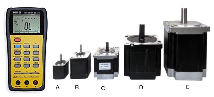
Using an LCR meter, we can measure resistance and inductance of the motor’s phase coils at varying frequencies. This works by injecting a signal (and energizing the coil) and measuring the response. Note here that we can’t reach stellar accuracy because the motor isn’t a true inductor. When we energize the coils, the shaft moves and adds noise to the measurements. What’s important here is the trend.
Measurements were taken on the five motors shown above at different frequencies. Plotted below are the measured inductance (in millihenries) and resistance ESR (measured in Ohms) with respect to frequency. We’re using 1.8 degree stepper motors (by far the most common) and the equivalent RPMS are annotated by the vertical lines. Note that the maximum speed the Wi-Fi Stepper is capable of is 4500 RPM.
Stepper Motor Measurements
Frequency-dependent inductance and ESR
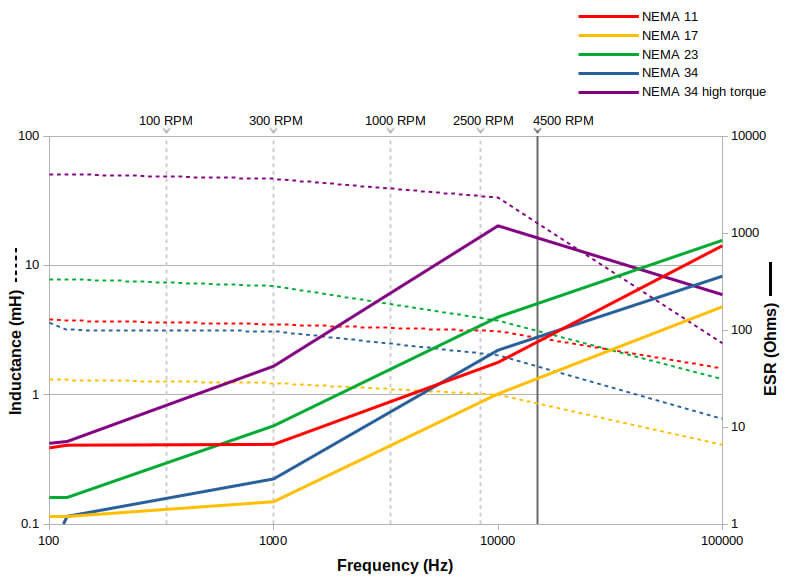
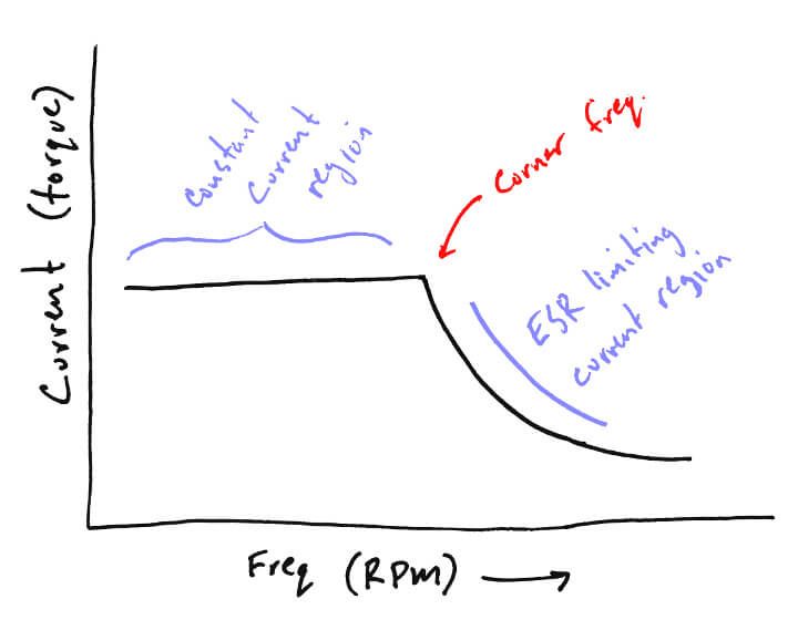
What’s really interesting in this graph is that it shows that the higher the frequency, the higher the ESR. Every stepper motor has a point at which the current at higher frequencies is limited by this ESR. It’s physically impossible to drive the motor at the desired current above this point. As such, torque is limited too (since torque is proportional to current). This point is known as the corner frequency.
Below the corner frequency, current is limited by the stepper motor driver and your KTval setting. Above it, the ESR takes over and limits the current according to Ohms law V/R (the R here being the ESR). An interesting aspect of this is that higher input voltages raise the corner frequency, and higher KTvals actually lower the corner frequency.
Why does the ESR increase with frequency? Eddy currents in the motor windings, as well as proximity and skin effect all play their roles.
Most stepper motors have datasheets that show a similar graph as the one above. It will list torque rather than current and also have a rated voltage and peak current.
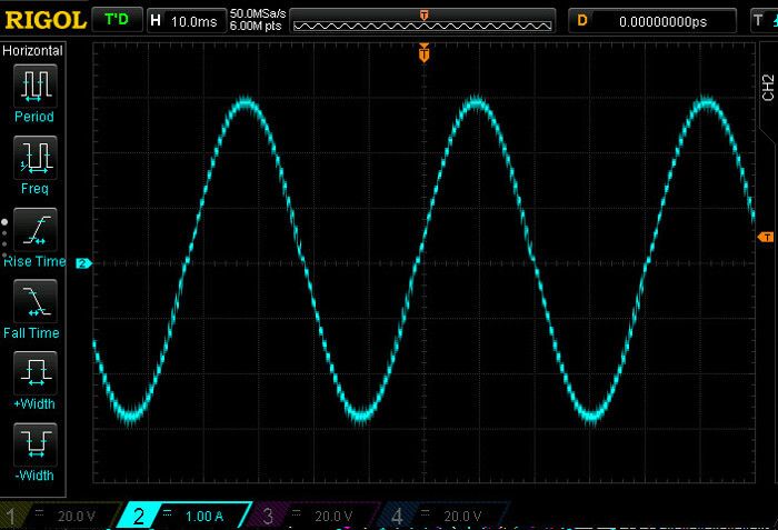
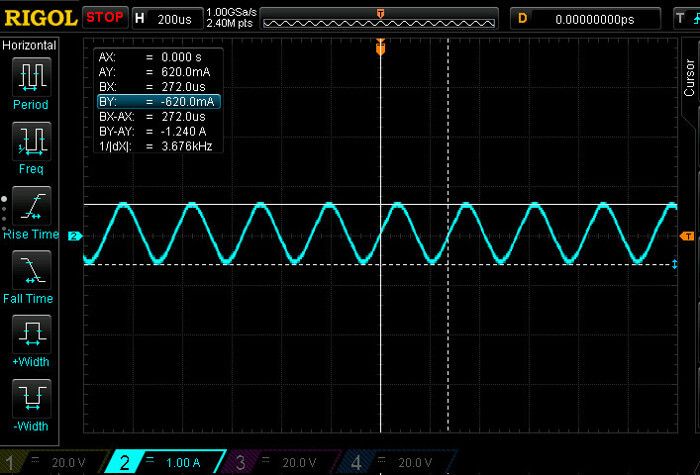
Finally, let’s actually show the ESR in action. In the first oscilloscope plot, we’ve hooked up the NEMA 23 to the Wi-Fi Stepper and set our KTval to 3 Amps. Running at 30 RPM, we are well in the constant current region of the current/frequency curve. This is where the stepper motor driver is limiting the current to 3 Amps using the current sense resistor feedback. In the next plot, we are running at 4500 RPM, our maximum speed. At this speed, our ESR is at maximum and our current is limited to one fifth of our desired 3 Amps.