Project update 2 of 7
Quick Start Guide
Physical Installation
To start using your Tarocco board, you need to make sure that:
- A 6 to 36 VDC power supply is connected to the board with the correct polarity. We recommend using a fuse
- A brushed motor is connected to the board
- A quadrature encoder is connected to the board. To protect the user and the equipment, Tarocco will not run the motor if it does not detect an encoder signal
- The logic side is powered
Powering It Up
When the logic side supply is connected, the two on-board LEDs will flash in lockstep for three seconds. The board is now in bootloader mode so you can use a USB-serial converter to update the firmware for your controller.
After the initial three seconds, only the VIN LED will remain lit. Tarocco is now in position control mode, and will respond to the step, direction, and reset signals. It will also be able to receive serial commands.
If the motor’s polarity is inverted when connected to the board, the controller will attempt to spin the motor in in the wrong direction. The controller will detect this and it will stop the motor while signaling a fault condition. You can correct this by reversing the motor’s connection or by setting the "direction of rotation" flag to "one" by sending the command r1;.
Serial Commands
Tuning the controller is straightforward: connect Tarocco to a USB-serial converter and open a serial terminal program. The commands that the board accepts are just an ASCII character, followed by an 8-bit numerical value (also ASCII) and ending with a semicolon. For example, c127; sets the current to half the maximum allowed value (5 A).
Tuning the Controller
For correct operation, you’ll need to adjust the PID coefficients for your particular mechanical setup. This is accomplished by sending three simple serial commands. Each coefficient should be an 8-bit value, a number between 0 and 255. The command starts with a lowercase ASCII p, i or d character (p is for the proportional coefficient, i is for the integral coefficient and d is for the derivative coefficient), then the 8-bit value for each coefficient, and lastly an ASCII semicolon. An example of a valid command is p123;.
By default, Tarocco will not transmit any diagnostic data back to your computer. However, by sending the command u1; you can get the position error data to help you in the tuning process.
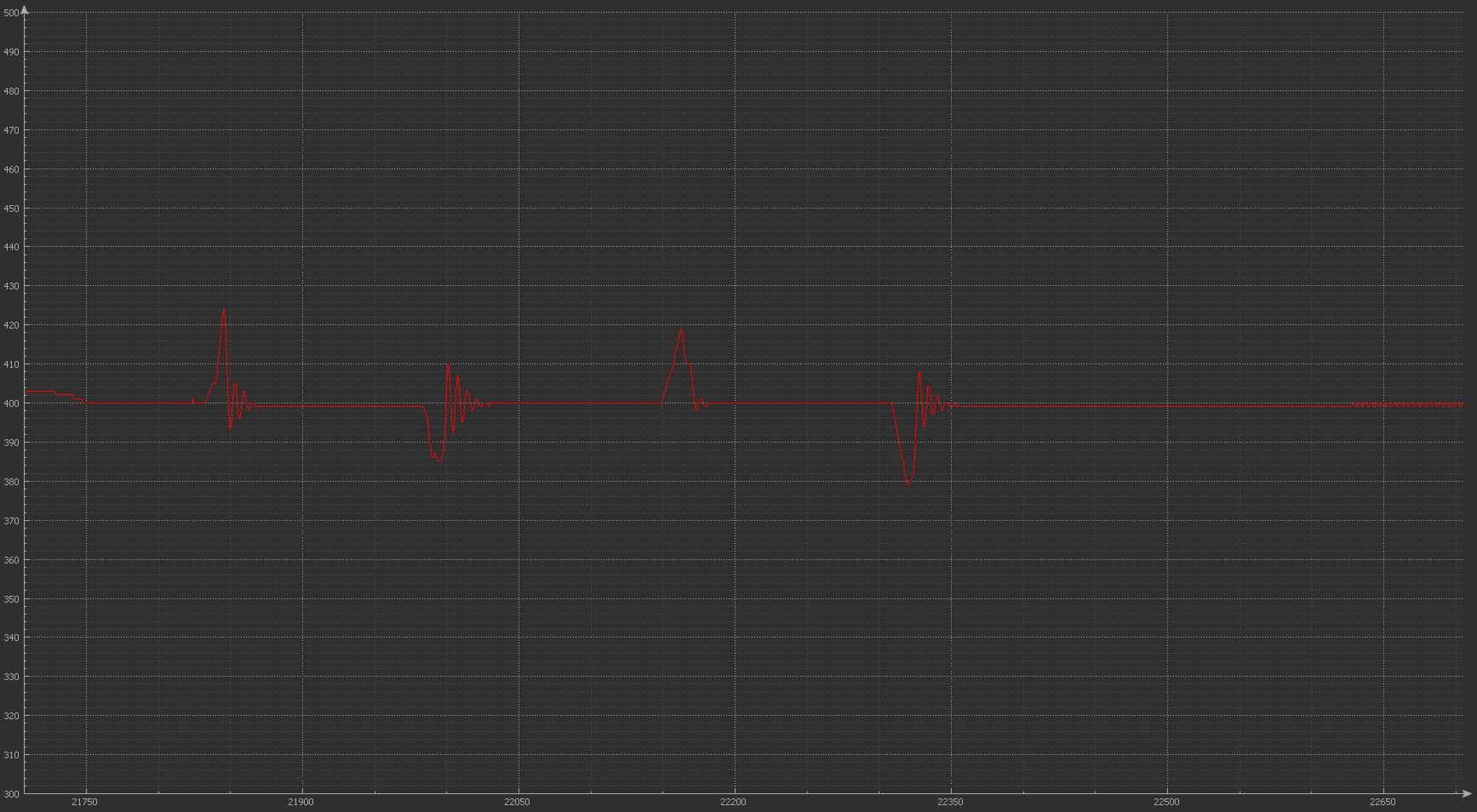
You can monitor the controller performance by using a serial plotting program (for Windows, we recommend the open source Serial Port Plotter). The error in encoder counts is transmitted in real time with a 400 count offset (a value of 400 means an error of zero counts).
With a correctly tuned motor and not very high speeds you can get your system to perform within five encoder counts of error. Rapid movements will have more error, but since you’re not cutting or printing anything it does not matter!
Stay tuned for more.