Despite the fact that our description of GetWired is quite long (though hopefully not too boring), it is nonetheless missing certain practical details about how to use the various GetWired modules. We believe that many of our backers and potential backers are curious about those details, and this update seeks to provide them. To that end, we have produced a Quick Launch Guide for the GetWired Basic Bundle.
Contents of the GetWired Basic Bundle
The Basic Bundle gives you the opportunity to test all current GetWired designs for the reasonable price of $130, which makes it a good entry-level proposition for anyone who wants to get acquainted with our affordable, open source, wired home-automation system. We strongly recommend adding a Programmer, Adapter, and Wires purchase to your basket as well. It will greatly facilitate your GetWired experience.
To the point, then. A Basic Bundle provides:
- A GetWired Ethernet Gateway with LED Enclosure Panel (the photographs below include a milled prototype)
- 2x GetWired MCU Modules
- A GetWired 2SSR Shield
- A GetWired RGBW Shield
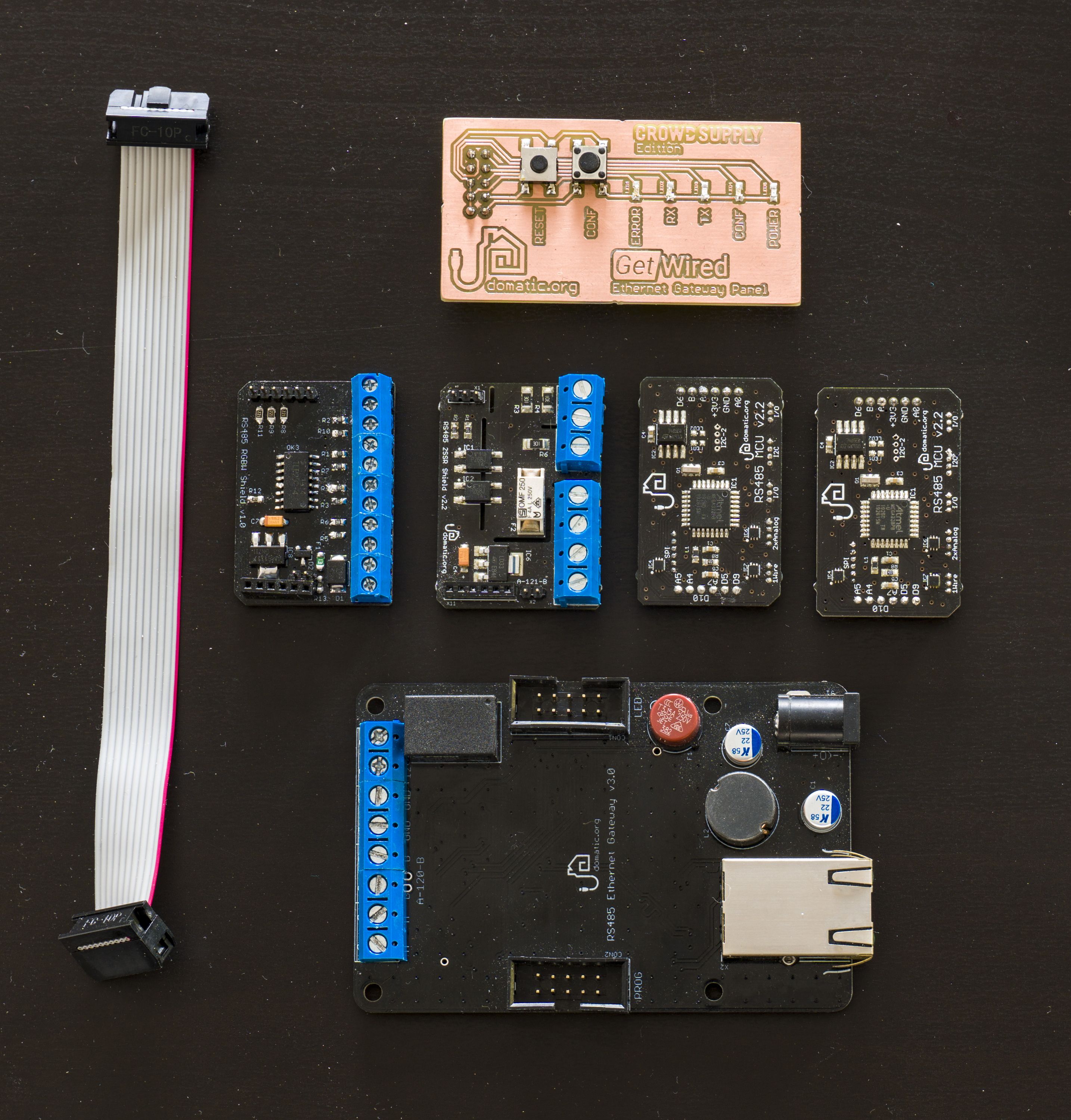
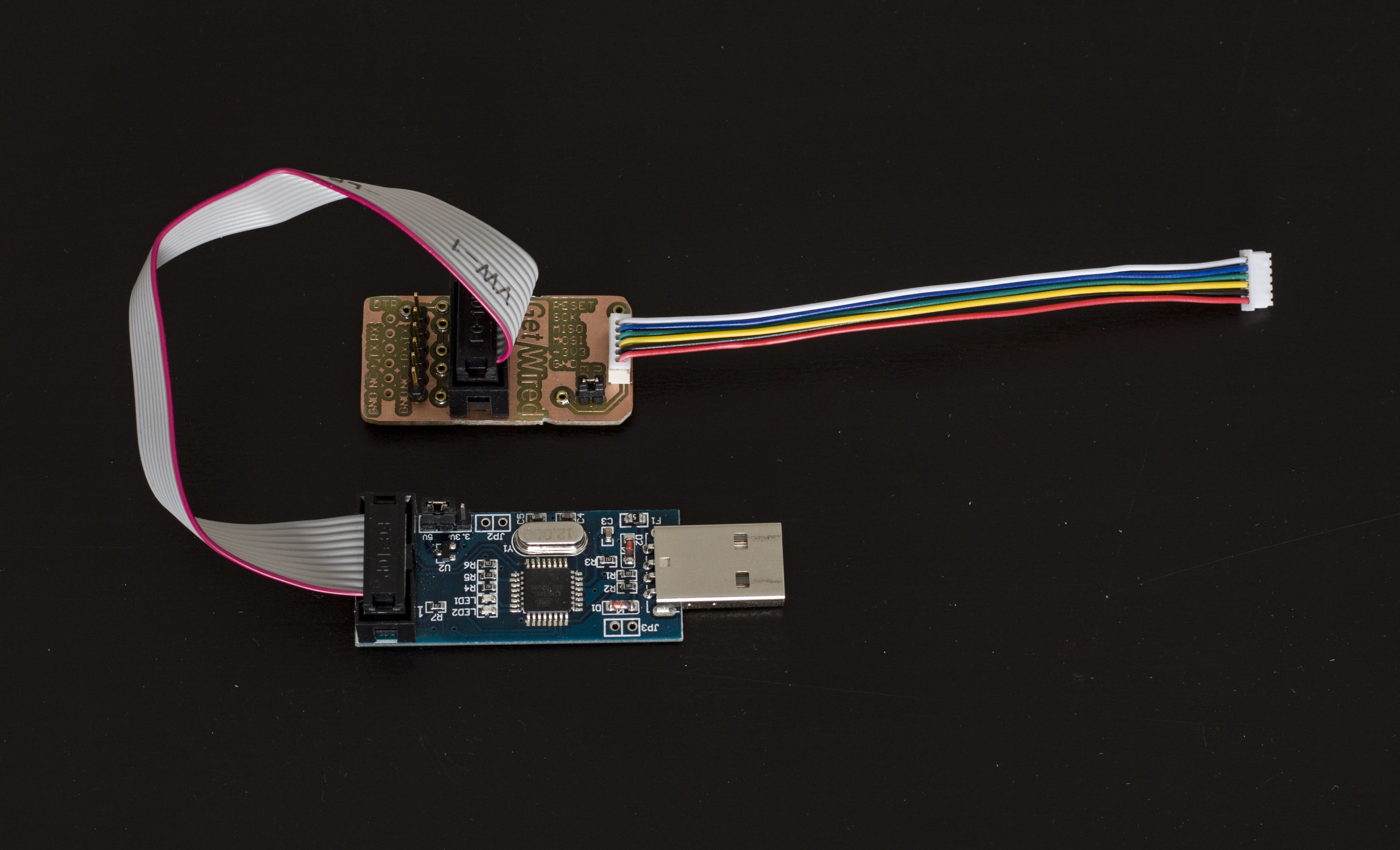
The Programmer, Adapter, and Wires will add the following to your collection:
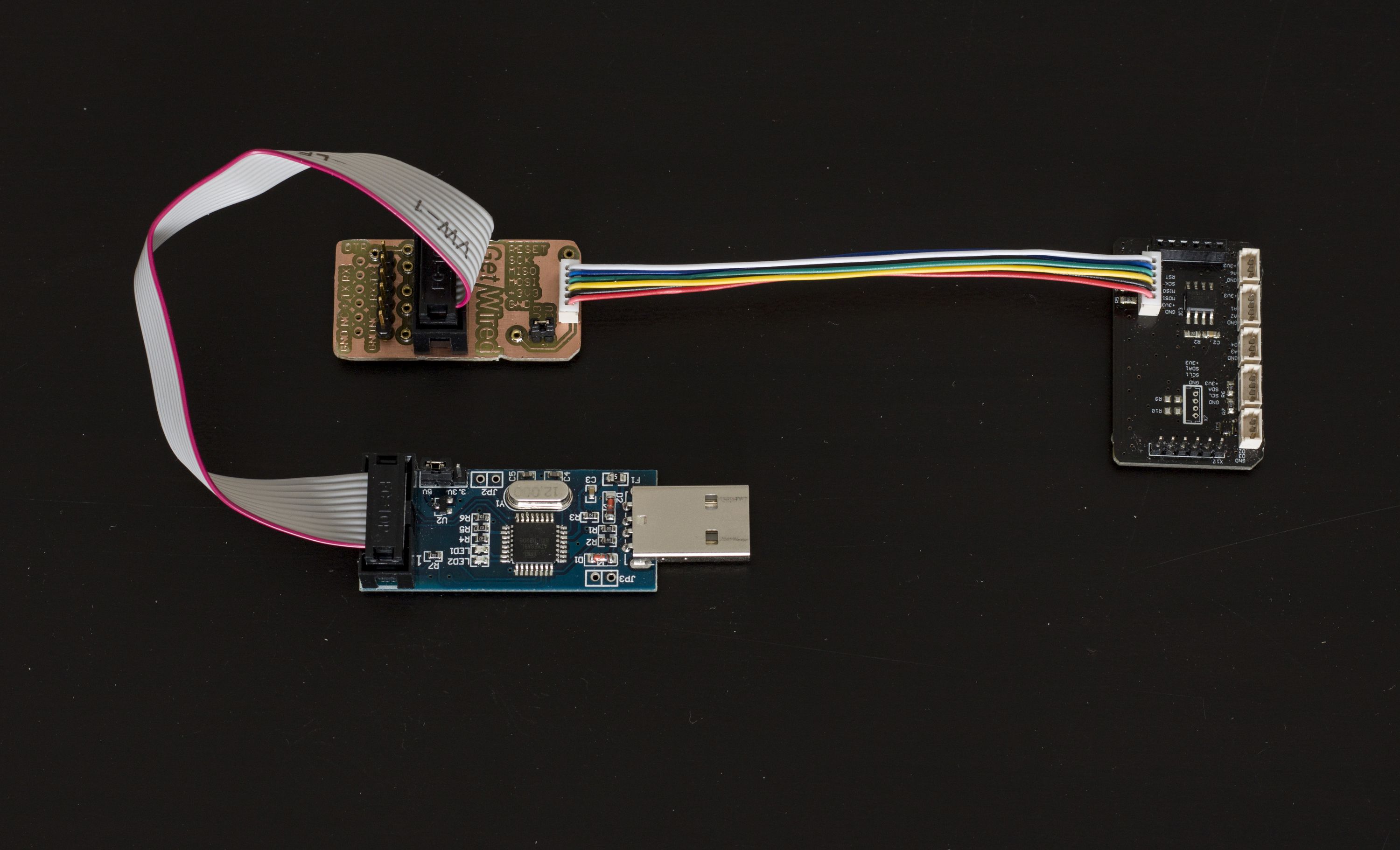
- A USBasp V 2.0 programmer with IDC cable (which some of you might already have)
- An MCU programming adapter with a 6-pin cable (which you almost certainly do not have, and which will save you from having to build one yourself)
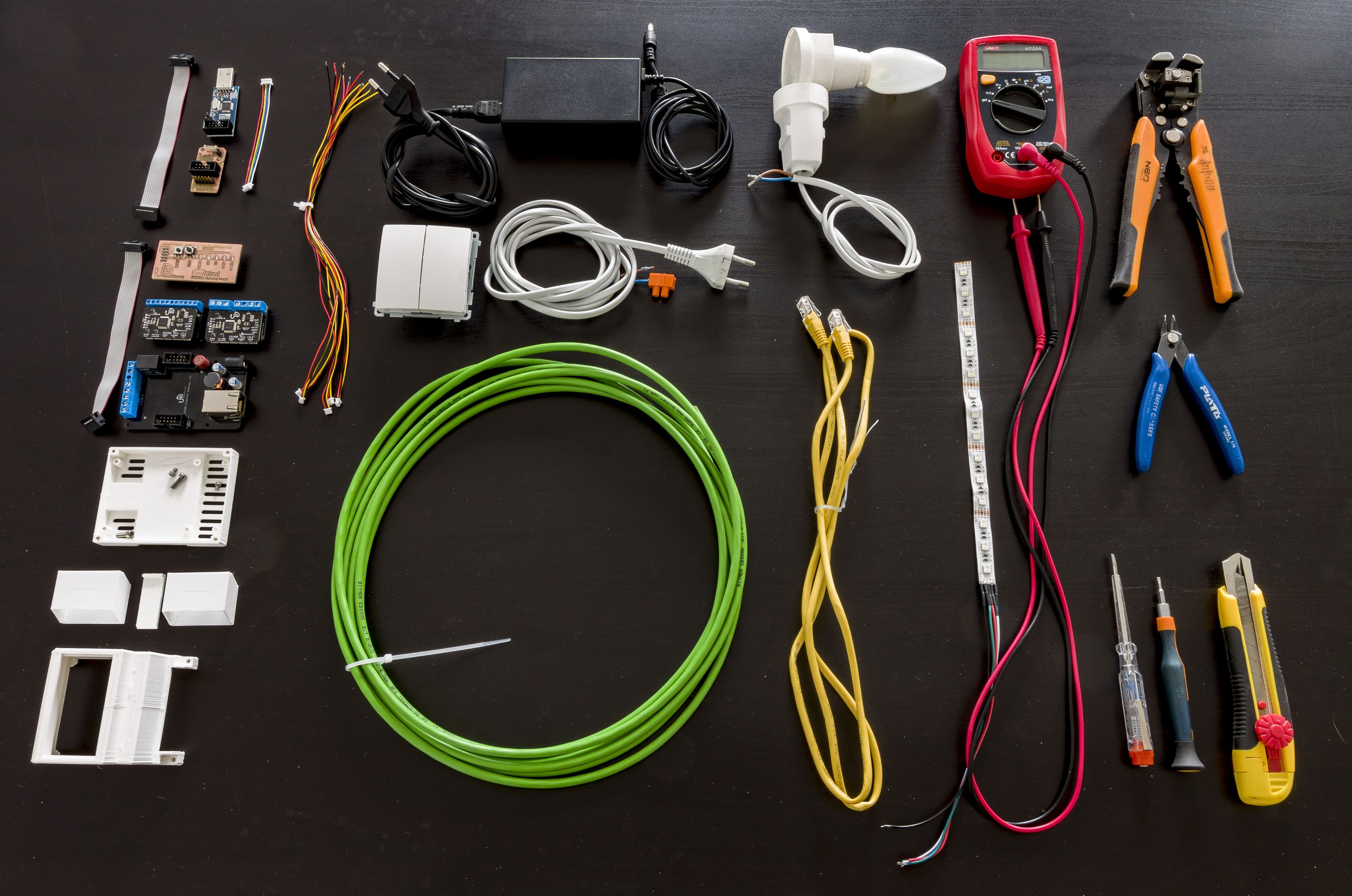
Other Important Gear
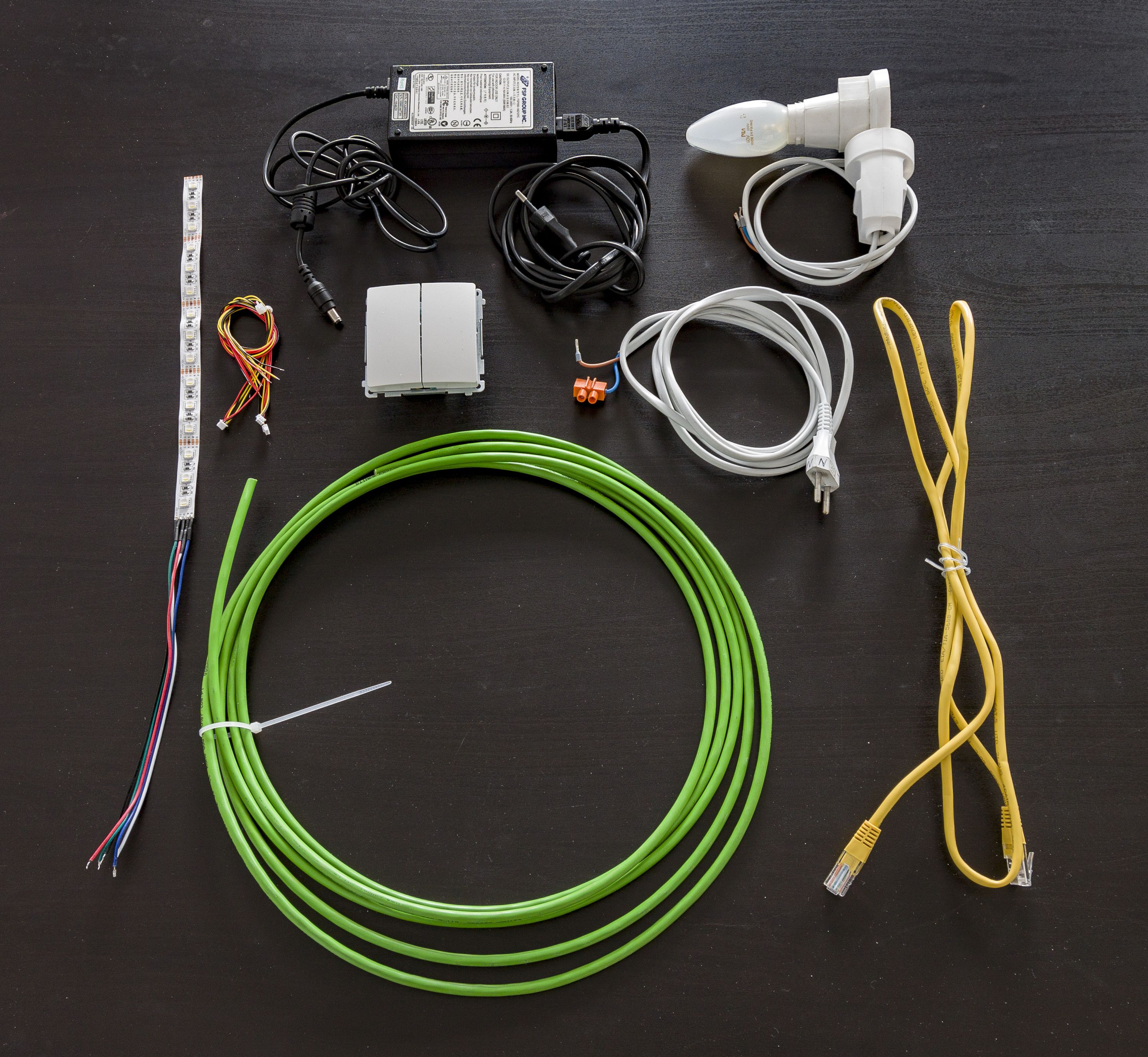
While our bundle includes all of the GetWired-specific products you will need to test our hardware, doing so will certainly require a few additional items. Fortunately, you can find most of this equipment online or in your local electronics shop or hardware store.
What we can do is provide a shopping list. So let’s have a look.
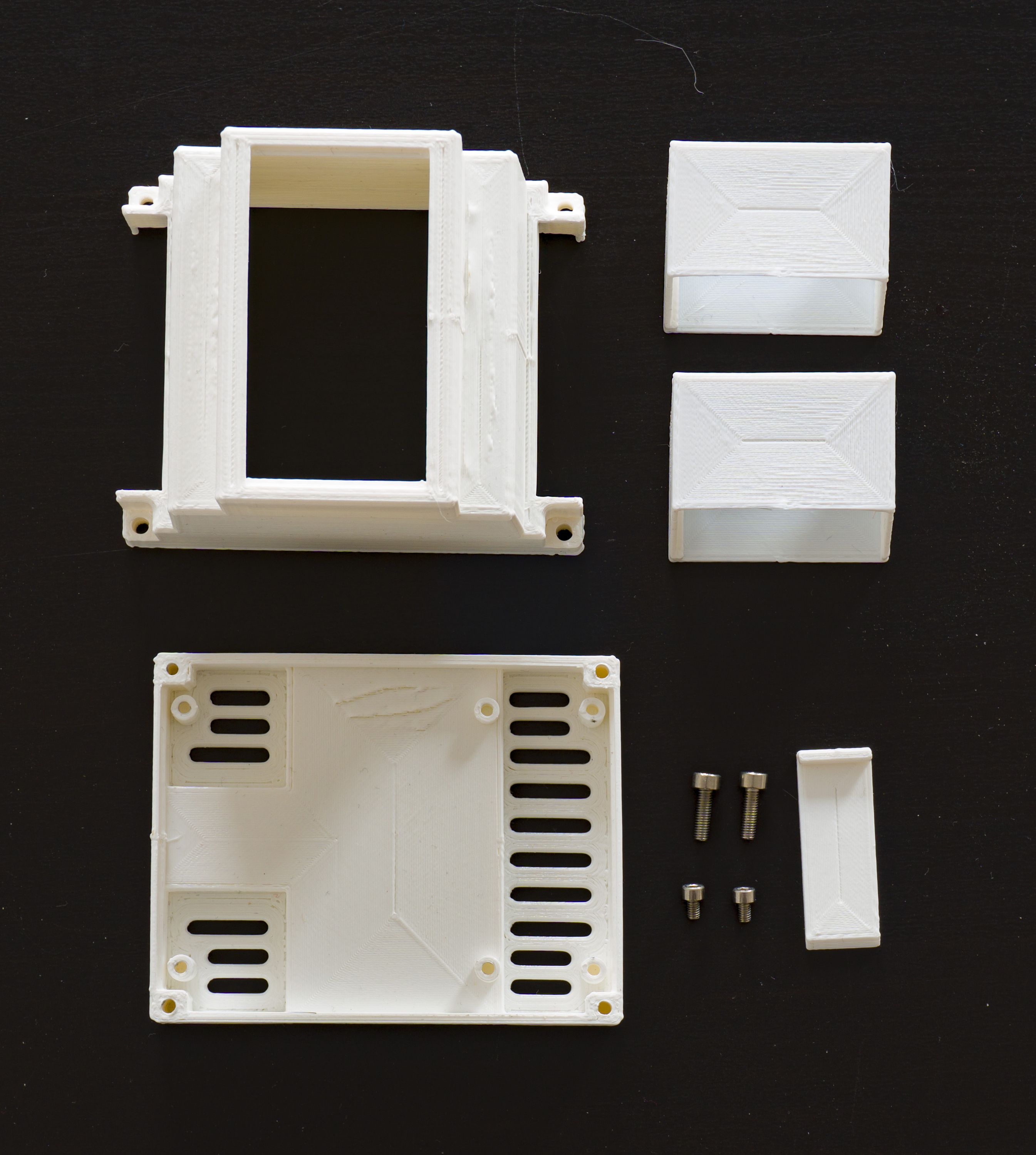
Making Enclosures
As mentioned in our previous update, we decided not to offer enclosures through the campaign, but to provide 3D-printable designs instead. You can now download those designs from our GitHub repository.
If you are following along at home, please download all of the .stl files and 3D print them as follows:
- 1x
GetWired Switchboard Case bottom.stl - 1x
GetWired Switchboard Case top.stl - 1x
DIN Rail Pin.stl(this is only needed for mounting the Gateway enclosure on a TH35 rail) - 2x
GetWired In-wall Case.stl
That will give you an enclosure for each board in the Basic Bundle. For the Gateway enclosure, you will need some hardware. We use:
- 2x M2.5x4 socket head cap screws (Allen bolts) to attach the Ethernet Gateway to the bottom part of the enclosure
- 2x M3x10 socket head cap screws (Allen bolts) to fasten the top half of the enclosure to the bottom
We also recommend gluing the Gateway’s LED Panel to the top half of the enclosure.
Buying Supplies
You will also need to find a few things at your local electronics shop or hardware store (or buy them online).
Power Supplies & Wires
- A 12 V DC, max. 3 A power supply with 5.5/2.5 DC plug (center positive) – something like this
- An Ethernet patch cord to connect the Gateway to your switch or router (the cheapest one you can find should work fine) – something like this
- A bit of cable to serve as an RS485 bus (for testing purposes, you could even use a cat. 5e data cable) – something like this
Receivers
For the RGBW Module
You will need:
- A white, RGB, or RGBW LED strip – something like this (white) or this (RGBW)
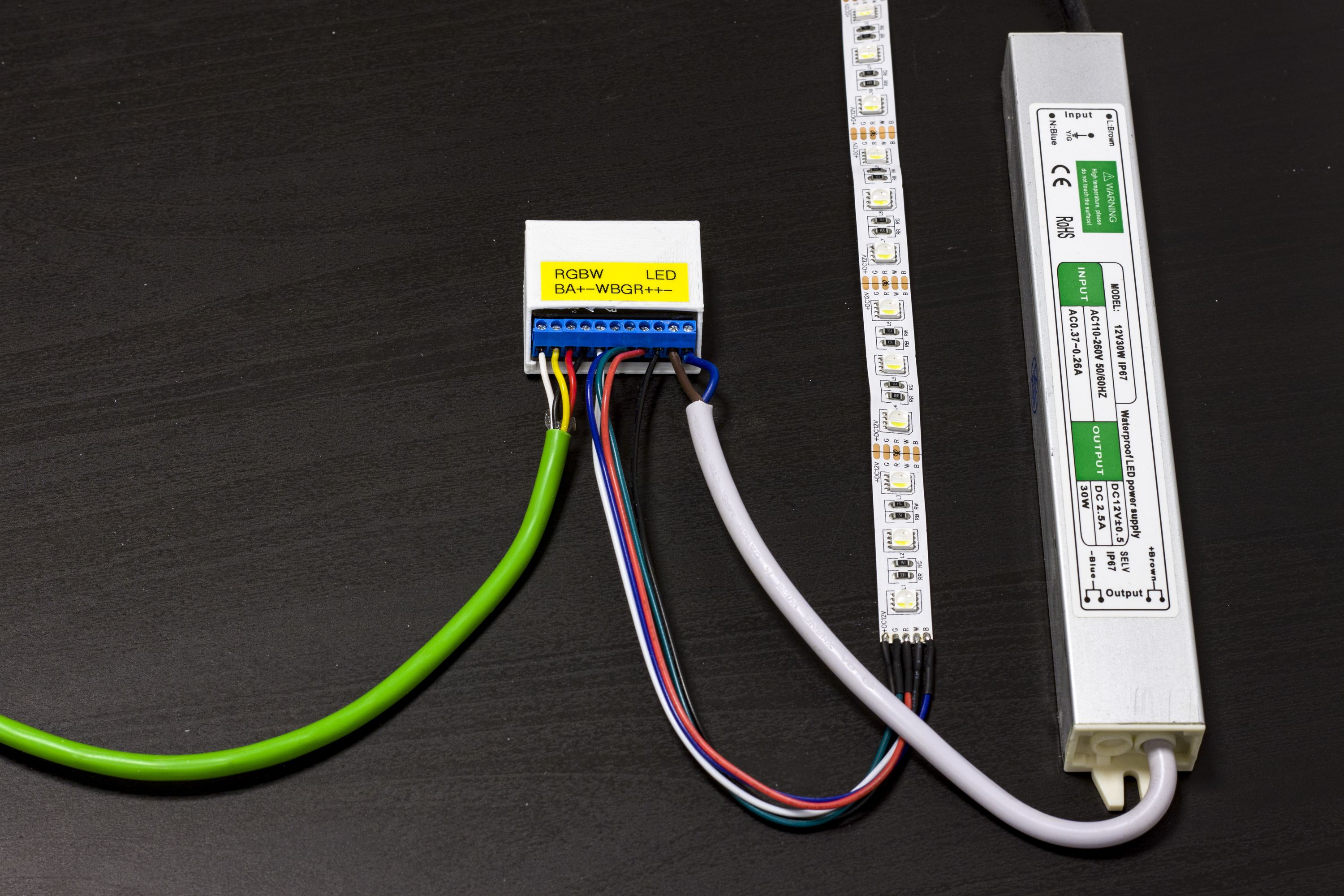
- An LED power supply (if not in a bundle) – something like this.
For the 2SSR Module:
You can use any AC light bulb or any roller shutter that does not exceed the 2SSR Shield’s maximum load. You will be working with AC power here, which can be dangerous. If you are not confident with that kind of voltage, please ask a qualified electrician for help!
Recommended Tools
The following tools will be exremely helpful during the assembly process, so you might also want to pick up:
- Wire strippers – available at Home Depot or Amazon
- A multimeter (I suggest the one with auto-range) – available at Home Depot or Amazon
- A precision flathead screwdriver – any of these should work
- Some cutting pliers – something like this
- A sharp knife

Wiring Things Up
Now that you have everything you need, let’s get down to it. This is where the real fun begins! (Though, if we’re honest, it’s all quite straightfoward. If you’re looking for more of a challenge, feel free to work in the dark until you get those LEDs working.)
Connecting GetWired Hardware…
Let’s start with the bus cable. You will need two pieces of wire, one for each module in the Basic Bundle. After cutting the wire into pieces (if this is a test run, try to keep the pieces short for your convenience), you should remove the jacket from both ends and strip the cores with your wire stripper. We only need four wires, so you can leave the rest as they are.
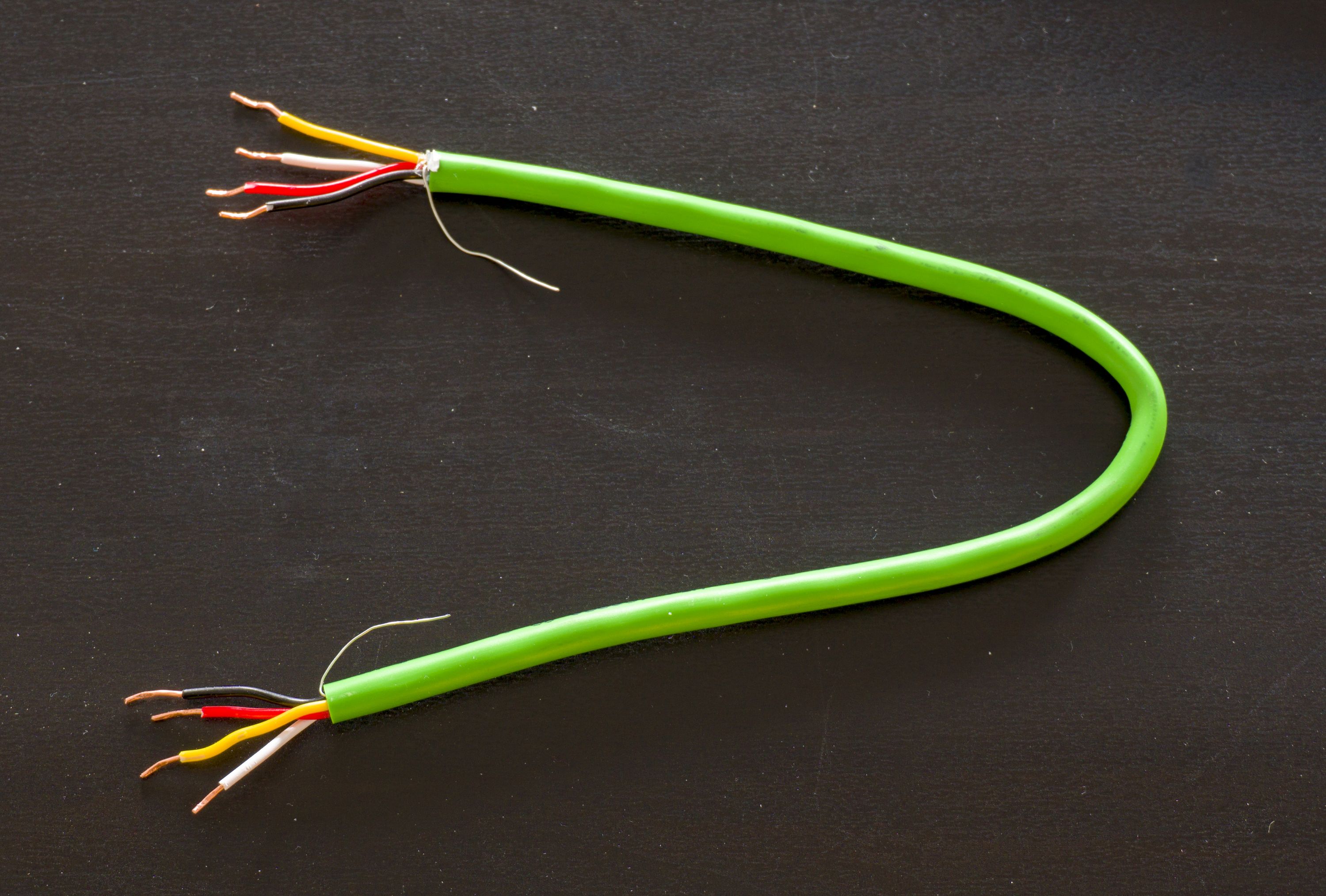
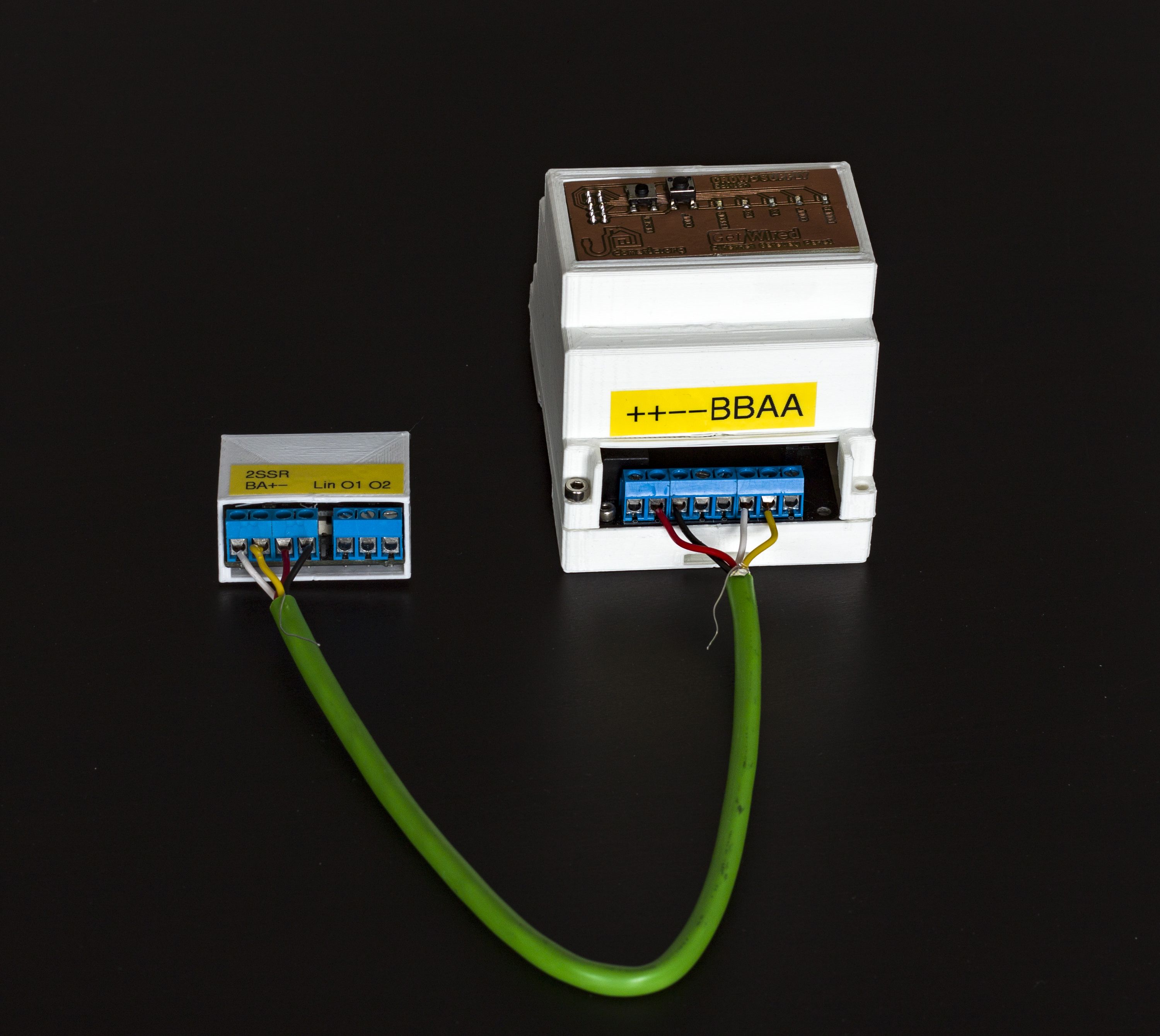
Now that the cable is ready, it’s time to connect your GetWired modules to one another and to your Ethernet Gateway. Not a big deal: connect A to A, B to B, +12V to +12V and GND to GND. Be careful not to swap the wires, though. Choose a color for each signal and be consistent.
…and Some Receivers
Now that your GetWired network is ready, it’s high time we gave it some receivers to play with. Let’s start with the RGBW Shield.
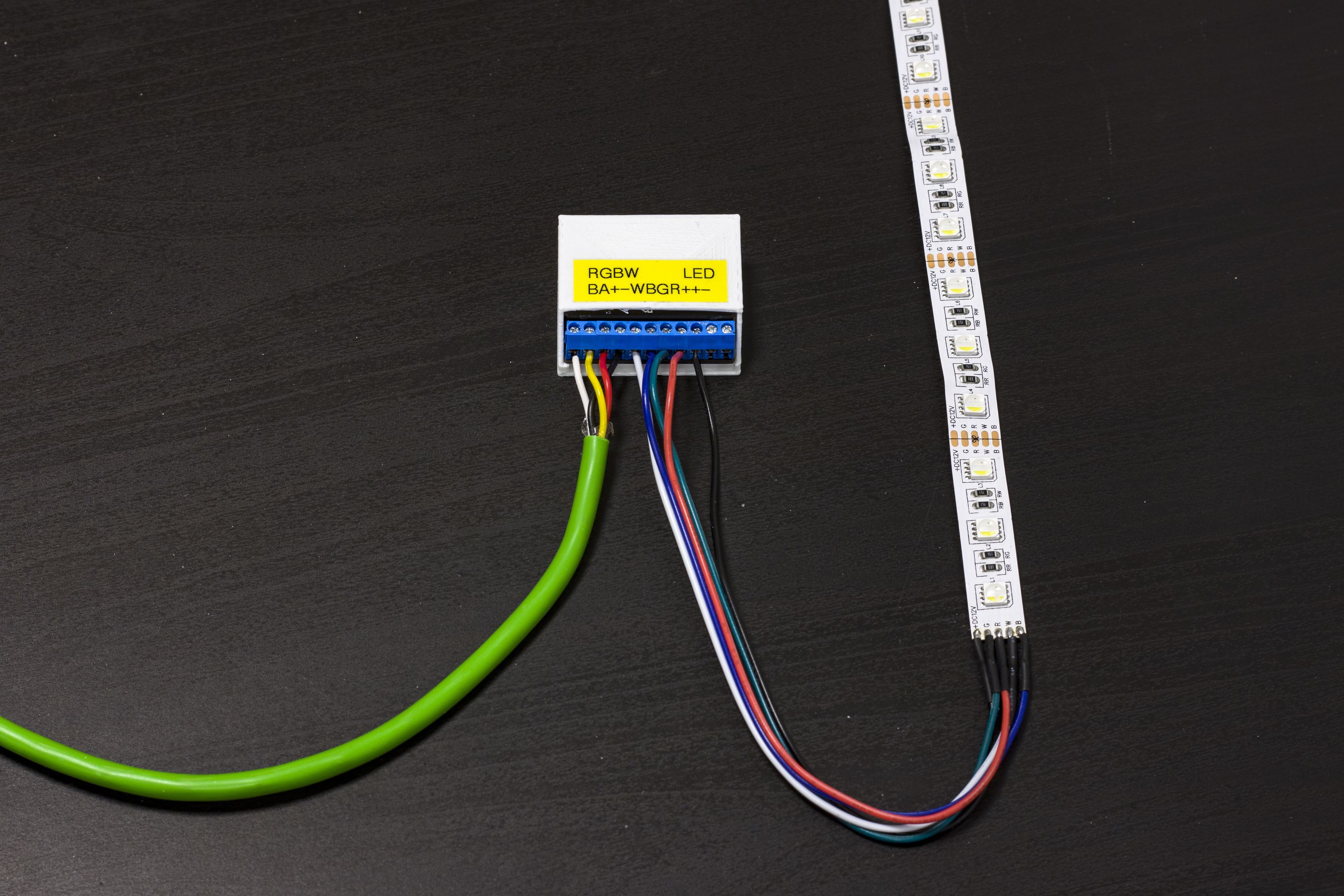
Connecting Receivers to the RGBW Shield
Connect R, G, B, W, and Supply wires to the module as shown below. (See the RGBW Shield pinout diagram for reference.) To preserve full galvanic insulation between the bus and the LED strip, you should use a separate power supply. There are special screw terminals for this: LED+ & LED-.
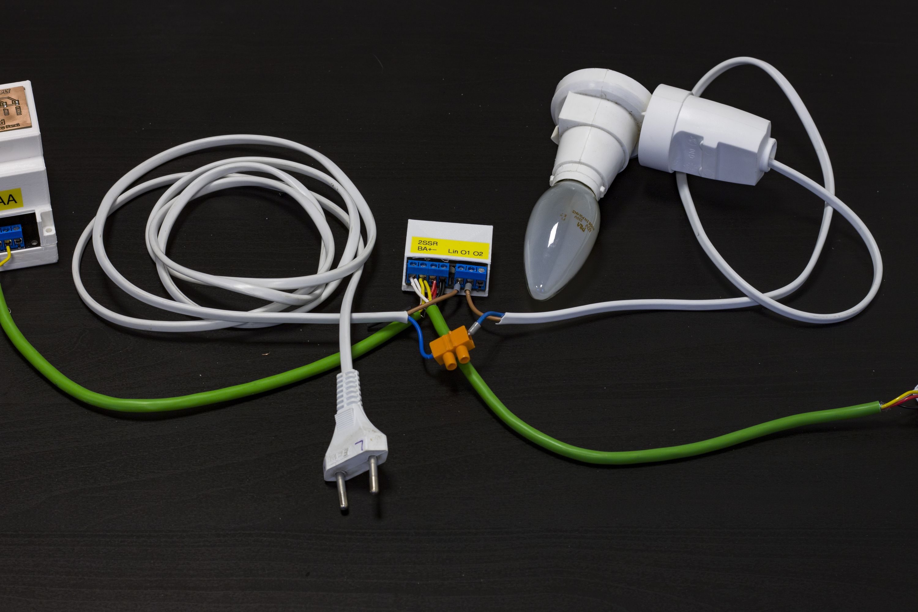
Connecting Receivers to the 2SSR Shield
Let’s move to the 2SSR Shield. As mentioned previously, we are working with AC power here, and AC power is dangerous. If you do not feel confident with this voltage, ask a qualified electrician for help.
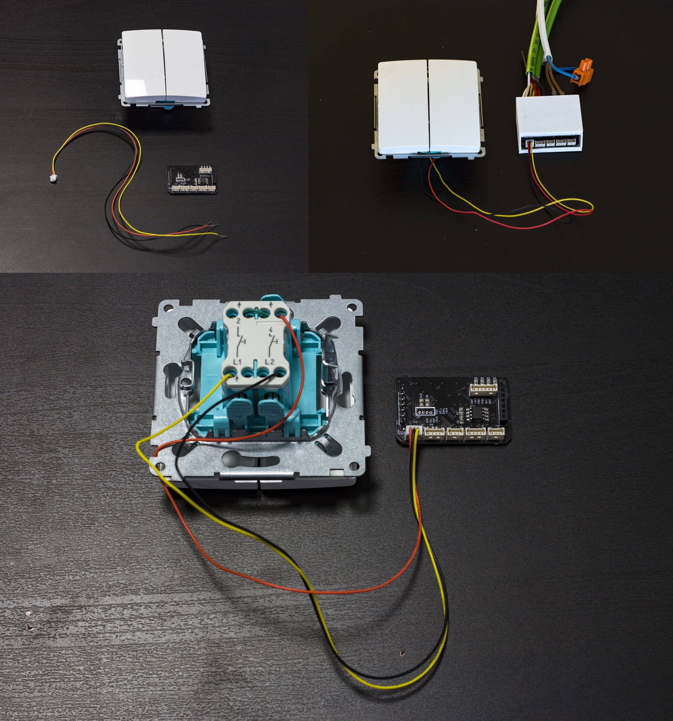
The 2SSR Shield needs only a live wire to work. Neutral wires should be connected outside the module with a quick splice or an external screw terminal. The 2SSR Shield works with a switch by default. It is the best to use normally-open switches, which should be connected to D2 and D3 as shown below. (See the 2SSR Shield pinout diagram for reference.)
Programming Your MCUs
After wiring it all up, we can move on to programming our modules. First, download the code from here. Once you have the code, all you need to do to get it working is edit an easy-to-use Configuration.h file. We’ll take a look at a few lines of that file below. Lines that are not mentioned are not relevant for the purposes of this tutorial and should be left unaltered.
Identification
The first edits you will make to the configuration file serve to identify the module:
MY_NODE_ID(Node ID) – A unique number (every module must have a Node ID, and no two modules connected to a given Gateway can have the same one)SN(Sketch Name) – Whatever you like (but we recommend keeping it short and distinctive)SV(Sketch Version) – Firmware version (has no effect)
// Identification
#define MY_NODE_ID 1
#define SN "GetWired 2SSR Module"
#define SV "1.0"
Definitions
We also need to set a few general definitions:
MAX_CURRENT– A value in Amps (set to 3 for 2SSR and to 10 for RGBW)MVPERAMP– mV per Amp of the current sensor (set to 185 for 2SSR and to 100 for RGBW)RECEIVER_VOLTAGE– Voltage of a receiver connected to your module (set to 230 or 110 for 2SSR and to 12 or 24 for RGBW)DIMMING_STEP&DIMMING_INTERVAL– Play with these values to achieve different transition effects with your RGBW moduleUP_TIME&DOWN_TIME– Roller shutter up and down movement duration in seconds (auto-calibration is not yet functional). Relevant only if you are controlling a roller shutter with your 2SSR Module.
// Power Sensor
#define MAX_CURRENT 3          // 2SSR - 3; RGBW, 4RelayDin - 10 [A]
#define MVPERAMP 185           // ACS7125A: 185 mV/A; ACS71220A: 100 mV/A
#define RECEIVER_VOLTAGE 230   // 230V, 24V, 12V - values for power usage calculation

// Dimmer
#define DIMMING_STEP 1
#define DIMMING_INTERVAL 10

// Roller Shutter
//#define RS_AUTO_CALIBRATION
#ifdef RS_AUTO_CALIBRATION
  #define CALIBRATION_SAMPLES 2
  #define PS_OFFSET 0.5
#else
  #define UP_TIME 21
  #define DOWN_TIME 20
#endif
Output Config
This one is actually quite important. This is where you will configure your output modes. Note that only one output mode can be active at a time.
DOUBLE_RELAY– Uncomment to use your 2SSR Module as a 2-channel AC switchROLLER_SHUTTER– Uncomment if you want your 2SSR Module to control a roller shutterDIMMER,RGB,RGBW– Uncomment one of these, depending on the kind of the LED strip you are controlling with your RGBW Module
// 2SSR
#define DOUBLE_RELAY

//#define ROLLER_SHUTTER

// Dimmer / RGB / RGBW
//#define DIMMER

//#define RGB

//#define RGBW
Input Config
The parameters in this section allow you to configure the inputs your module will handle. Many of these input modes can be active simultaneously.
INPUT_1-INPUT_4– Digital inputs for various purposes (you can choose a mode of operation for each input by commenting out the correspondingPULLUP_Xdefinition)POWER_SENSOR– Comment this out if you do not want your module to report power usage dataINTERNAL_TEMP– Comment this out if you do not want your module to report temperature data from its built-in sensorEXTERNAL_TEMP– Uncomment if you want to attach an external temperature sensor to your module's 1Wire connector (right now only DHT22 is supported)
Important: For proper compilation of RGBW code, at least one digital input (such as INPUT_1) must be active.
// Digital input
#define INPUT_1
#ifdef INPUT_1
  #define INPUT_ID_1 4
  #define PIN_1 INPUT_PIN_3
  #define PULLUP_1
  #define NUMBER_OF_INPUTS 1
#endif

// ACS712 Power Sensor
#define POWER_SENSOR

// Analog Internal Thermometer
#define INTERNAL_TEMP

// 1wire external thermometer (e.g. DHT22)
//#define EXTERNAL_TEMP
Programming the Gateway
You can download the GetWired Ethernet Gateway code from our GitHub repository. It requires only a few minor tweaks:
MY_IP_ADDRESS– Set a static IP address for your GatewayMY_PORT– The default here is 5003, which works fine, but you can change it if you like
#define MY_IP_ADDRESS 192,168,0,10   // Gateway IP address
#define MY_PORT 5003                 // The port to keep open on node server
                                     // mode / or port to contact in client mode
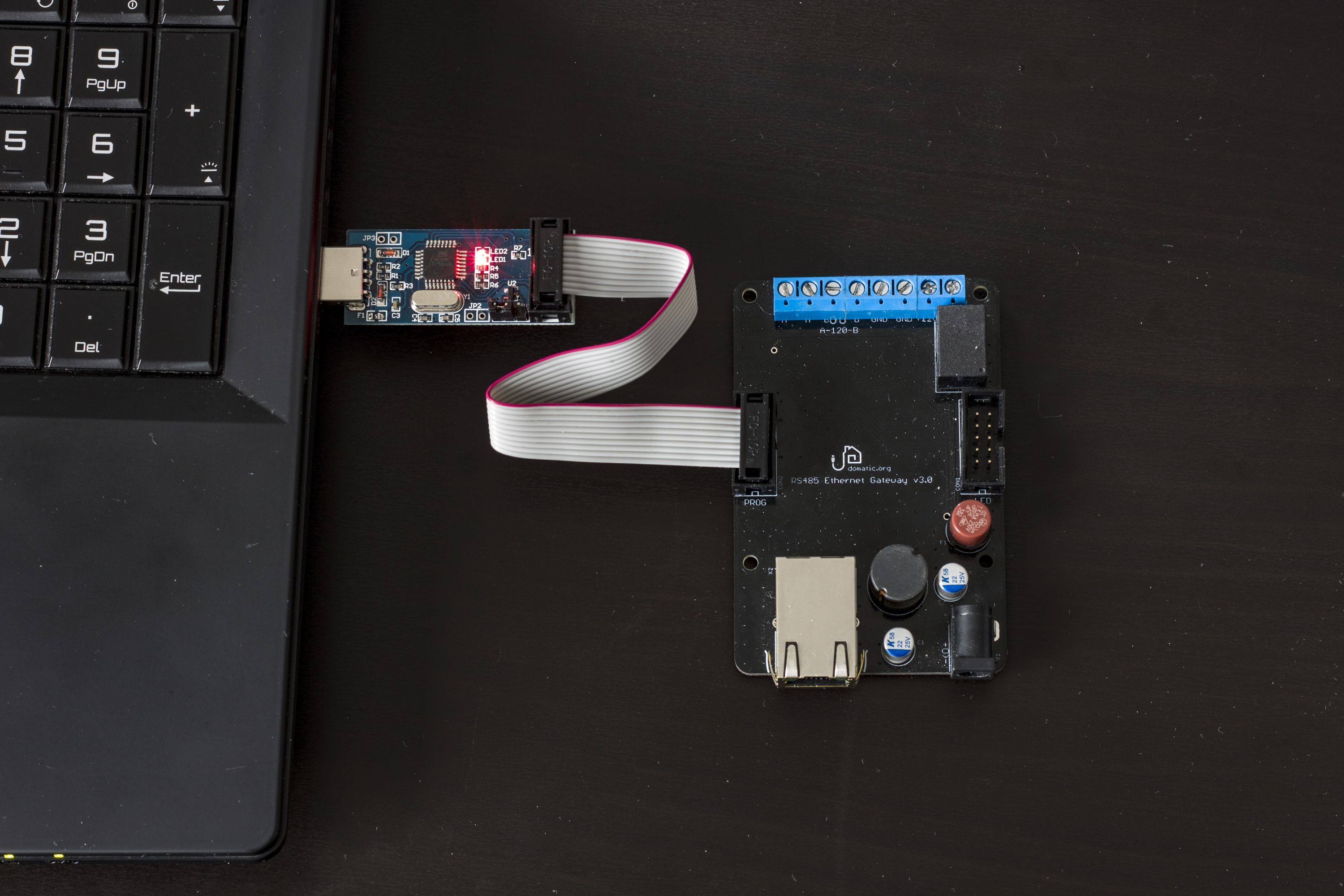
Flashing the Firmware With a Programmer
Now that you have your firmware ready, let’s flash it. The first thing you’ll have to do is add ATmega328PB controllers to the Arduino IDE. You can do this with MiniCore. Full instructions are available here.
A few things to keep in mind:
- When selecting the board, you have to make a few adjustments (see the picture and the table below)
- Firmware can be flashed directly from the Arduino IDE (Tools → Programmer → USBasp followed by Sketch → Upload Using Programmer)
- Set the programmer voltage to 5 V for the MCU (the MCU adapter has its own power regulator) and to 3.3 V for the Gateway
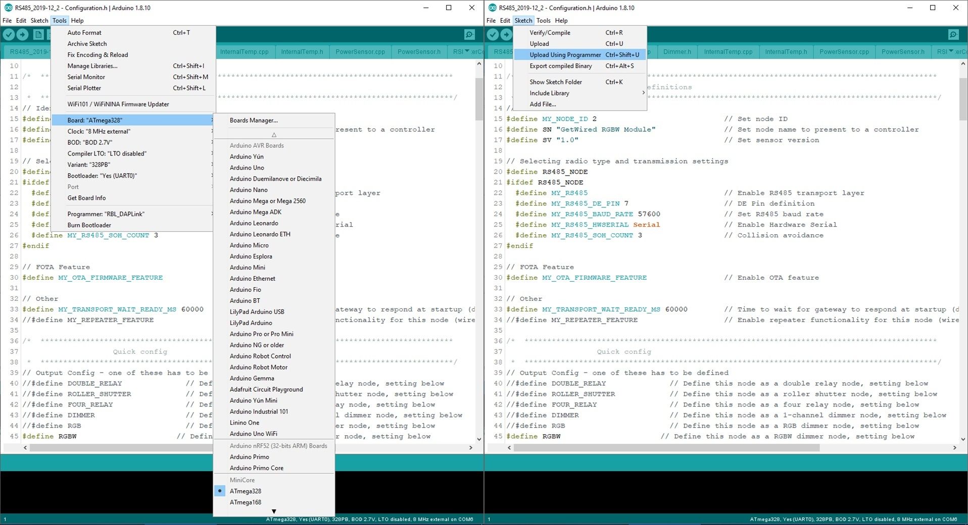
| Board Settings | MCU | Gateway |
|---|---|---|
| Board | ATmega328 | ATmega328 |
| Clock | 8 MHz external | 8 MHz external |
| Variant | 328PB | 328PB |
| Bootloader | Yes | No |
Now that it has been flashed, your MCU is ready to be assembled with a shield. You should do this while power is cut off from the bus. To cut power, press the CONF button on the Gateway’s enclosure panel. The CONF LED should light up. Press the same button again, after assembly, to bring the power back (and turn off the the CONF LED).
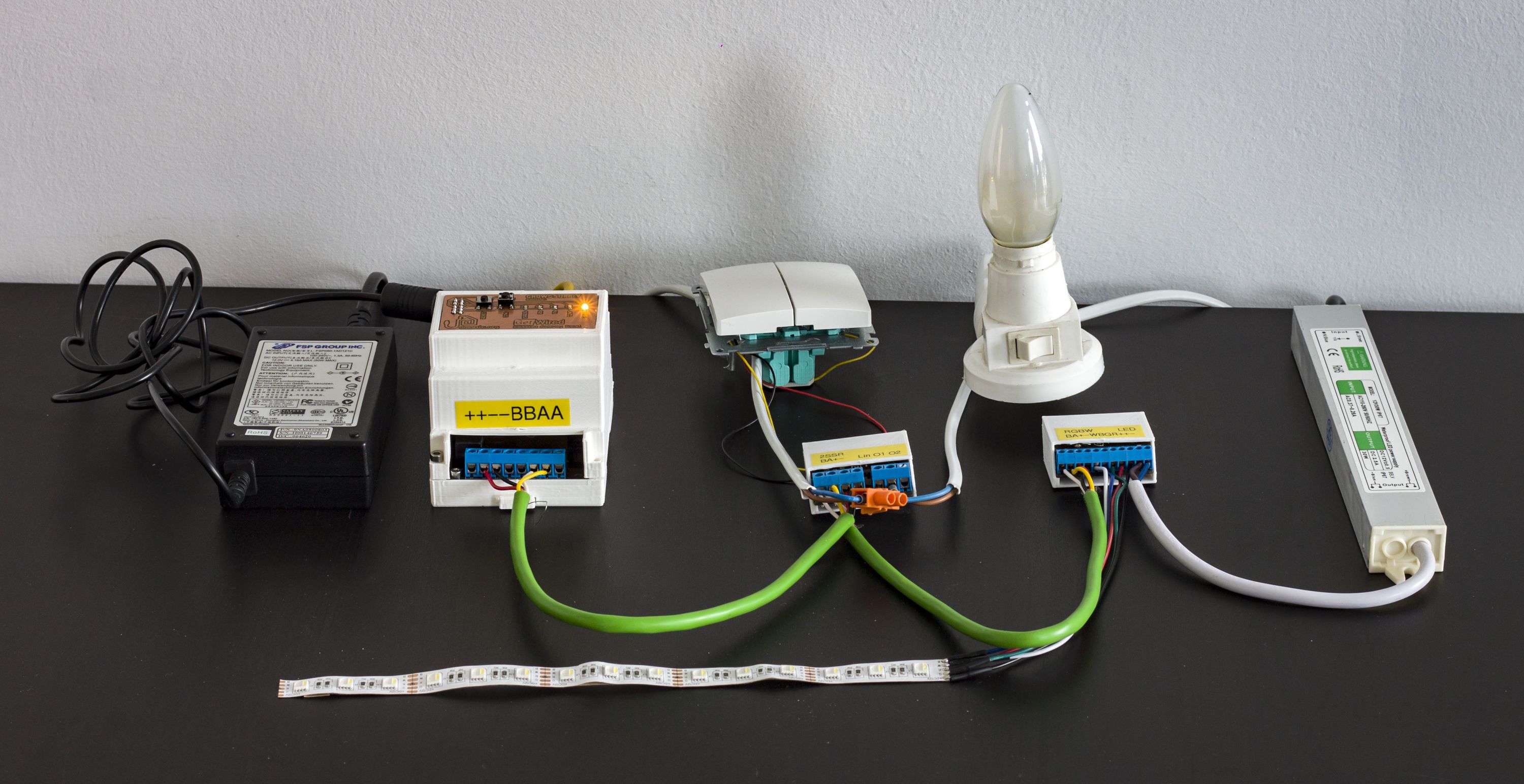
Conclusion
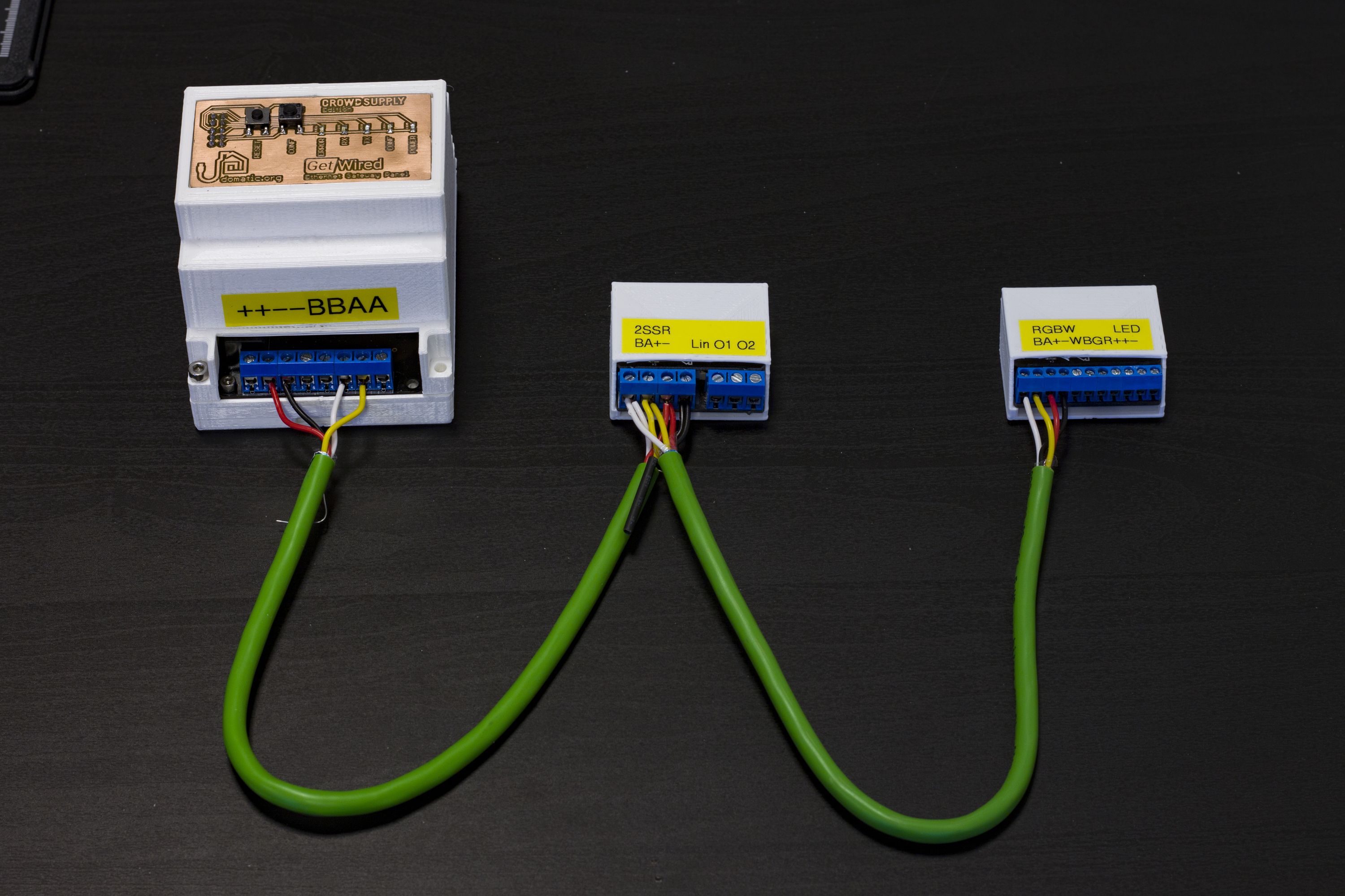
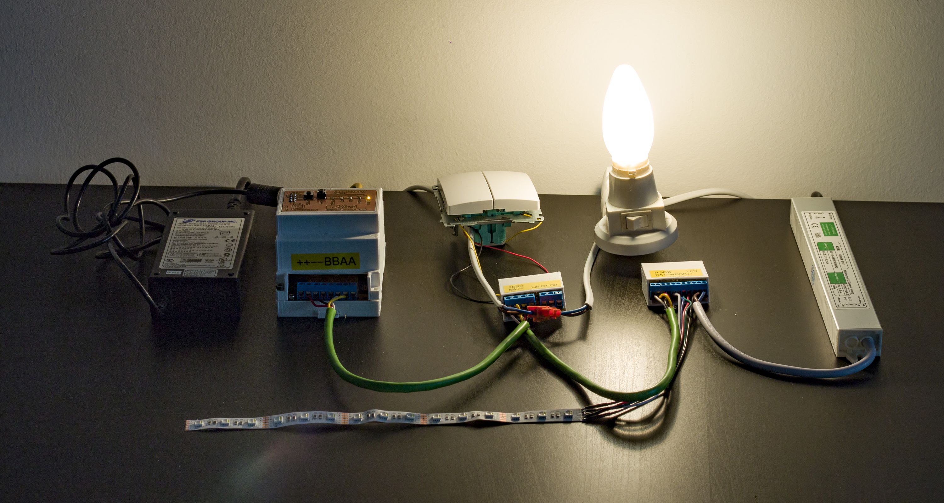
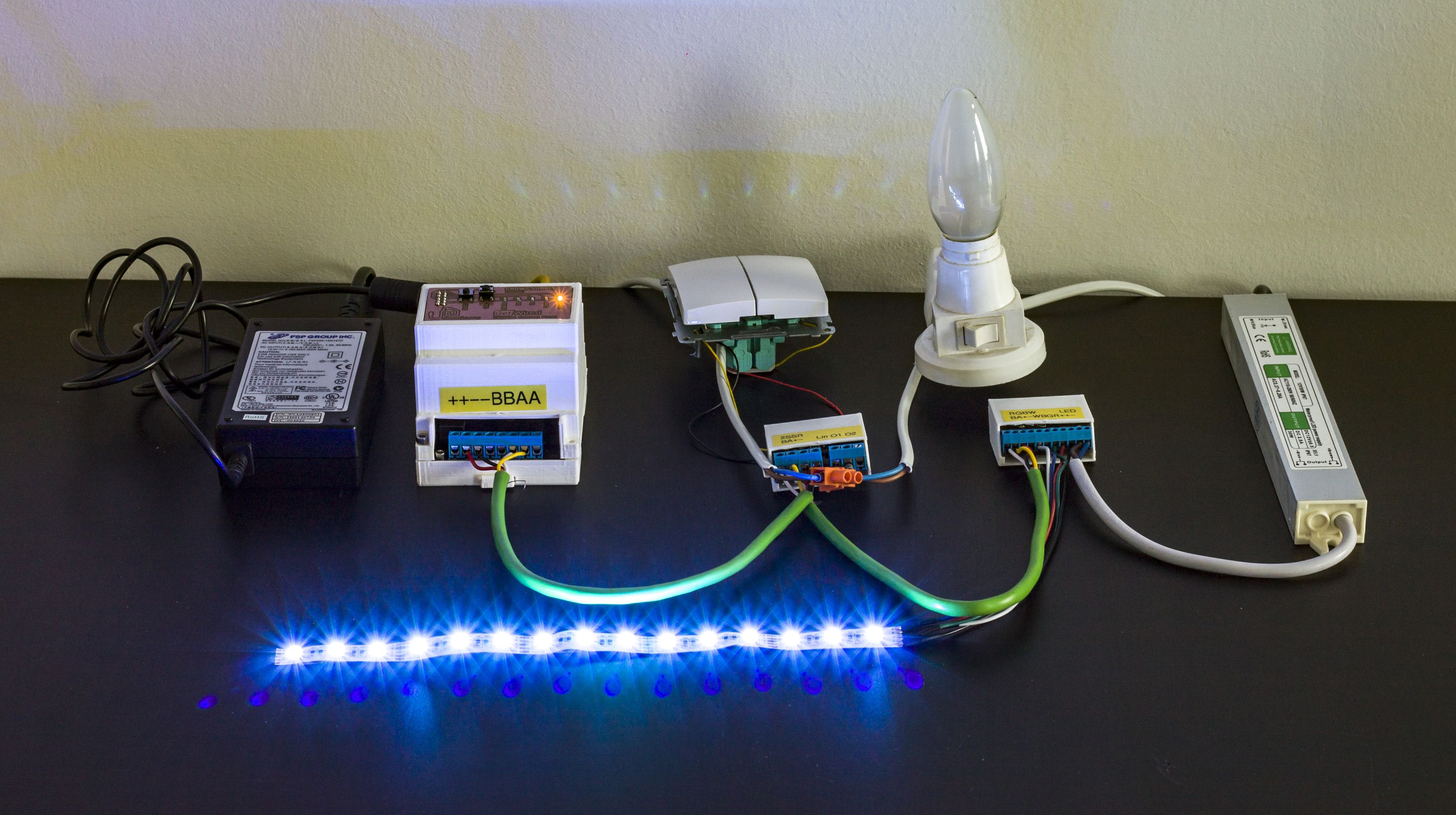
After you complete this tutorial, your Basic Bundle should look similar to the one shown below.
Despite all the information contained in this guide, we still have a lot more to cover in the future. Please consider this a place to start. Subsequent updates will go into greater detail on:
- Using GetWired hardware with Domoticz and Home Assistant
- Planning a GetWired installation in your home
- Preparing electrical installation for GetWired system
Thank you for reading. Please let us know if anything is unclear. And stay tuned for our next update!
Meanwhile, keep calm and support GetWired!