W00t! Snekboard is 150% funded! Thanks again to all of our supporters; you made this possible. We’ve been busy getting ready to start manufacturing boards, cables, and sensors, but we also found some time to develop a PID controller for the Line Bug we introduced a couple weeks back. We learned a lot in the process, and this update walks you through it.
Making the Line Bug Smarter
Lesson 2 shows you how to build a simple “Line Bug”, which wanders around a table following the edge of a black (or white) line. A few years ago, while we were still using C++ on Arduinos, one of the teaching assistants for the robotics class wanted to try applying more advanced robotics control techniques and see how much better it could work.
I’d heard of a control mechanism called proportional-integral-derivative (PID) and suggested to the student that they could go figure that out and give it a try. A few weeks went by and the student came to class with a bunch of C++ code that looked plausible, and we spent an hour fixing a few bugs and got it mostly working. The student spent another couple of weeks of tweaking the parameters and the line bug was zipping around our course quite smoothly.
While browsing for sensors to include in the Snekboard Sensor Kit, I found an 8-element reflectance sensor array from Pololu. I wondered if this might make an even better line bug sensor as it would provide a wider field of vision and let us know ‘how far’ away the edge line was from the centerline of the robot.
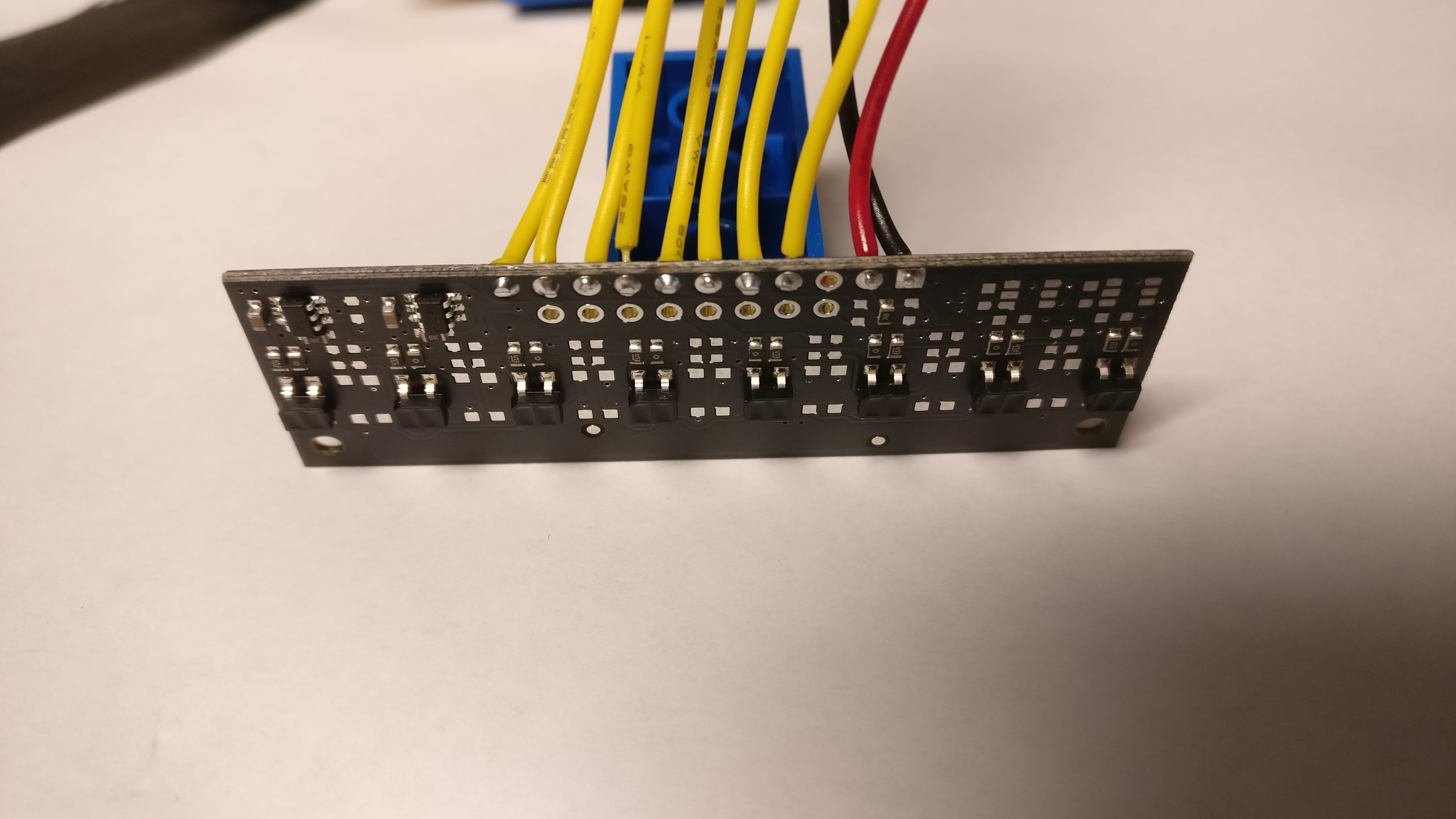
Hooking Up Eight Sensors
I wired the sensors up so that they were connected across Snekboard from right to left. Then I hot-glued the sensor PCB to the end of a 4x2 LEGO brick and stuck that on the front of the robot.
Black is Not Always Black Enough
The Pololu Sensor Array uses IR light, which means we’re looking for a two materials, one of which reflects IR light well and one which absorbs it. White paper is a fine reflector, but when I tried a black marker, that turned out to reflect IR about the same as the paper.
So I headed off to the local craft store and bought a selection of black paints, including poster, tempera and acrylic. Painting blobs of each on paper showed that the acrylic was the best absorber, producing a value of 0.77 while the white paper was 0.06. The poster paint only read 0.53, while the tempera was 0.70.
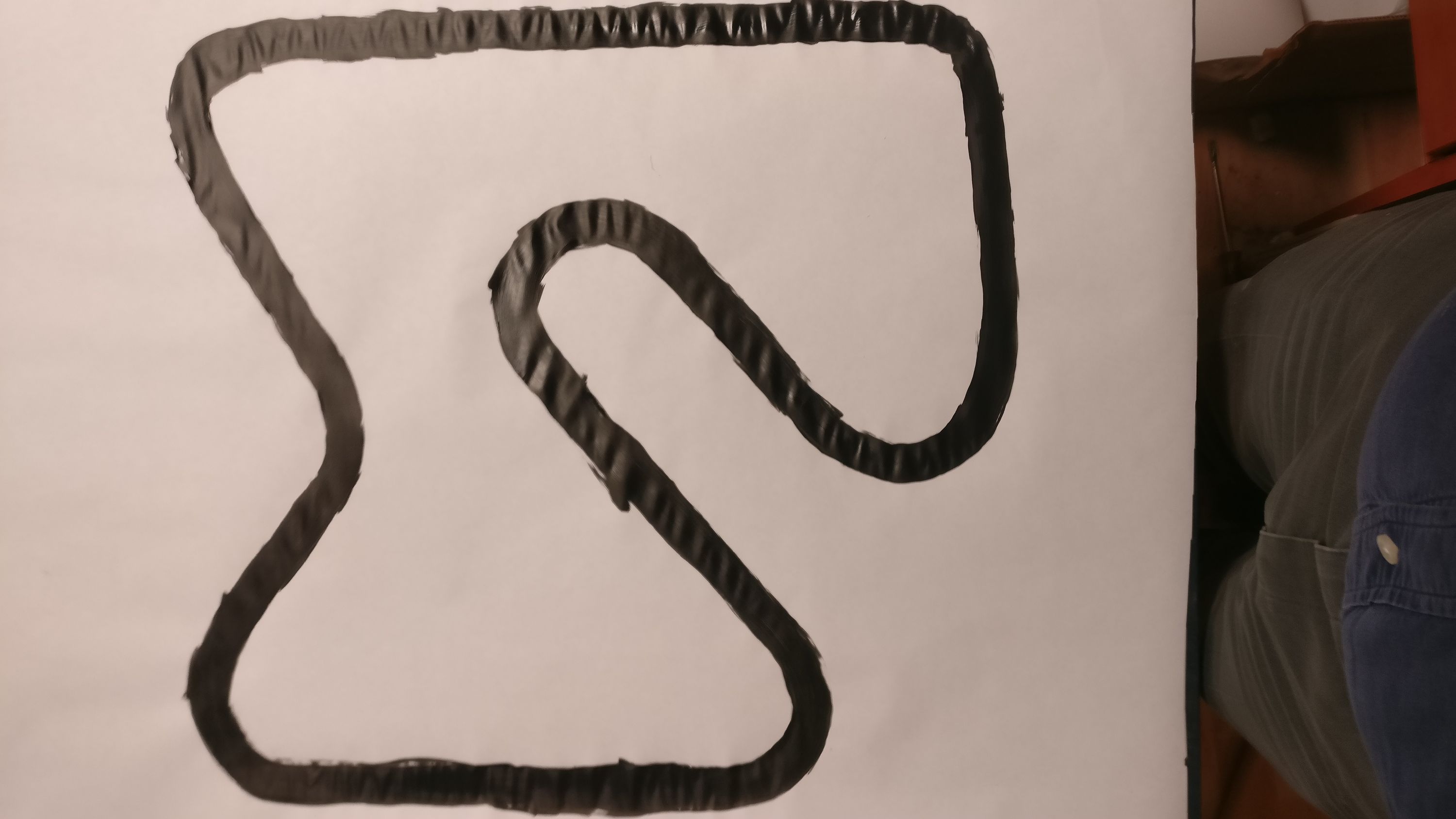
Creating a Track
I took the black acrylic paint and created a nice track for my line bug on a big piece of white paper taped to the table.
Classic Line Bug Test
Just for comparison, I took our classic “bang-bang” line bug code and implemented it on this robot:
PID Error Term
A PID controller takes an input value, called the “error”, and uses that to adjust the output value, called the “process value”. The controller is supposed to adjust the process value so that the error value is zero.
That means we want an error value which is zero when the middle of the line bug is over the edge of the black line. When it’s on one side of the line, we want positive values and when on the other side, we want negative values. The further from center, the larger the magnitude of the error term should be.
Because the line is not as wide as the sensor array, I needed to look for the ‘first’ edge and ignore any others. So I scan the sensors and stop when the first one is over the line:
def measure():
    error = -1

    # Start from the rightmost sensor and work leftwards
    # to determine where the edge appears.

    for s in range(A1,A8+1):
    v = read(s)
    if v > threshold:
        return error
    error += 0.25
    return error
This returns a value from -1 to 1, depending on which sensor first sees black. It’s not very smooth though, as it doesn’t try to figure out how far from the center of the sensor the edge appears. We can improve this by using the amount of light reflected into the first sensor that sees the line. That’s just black - v. Let’s add that into the result so that we get a smoother answer:
return error + (black - v) / 2
Computing the Process Value
As the name implies, a proportional-integral-derivative controller uses three values:
- Proportional. This is just the error value.
- Integral. This is the sum of all previous error values.
- Dervative. This is the difference between the current error value and the previous error value.
Given these three values, the process value of the PID controller is computed using:
process = Kp * P + Ki * I + Kd * D
Kp, Ki and Kd are three magic constants which are provided to the algorithm by the programmer. Figuring out what these values should be is the hard part of the problem.
First Test
To make sure everything was working, I set Kp to 1, Ki and Kd to 0. This is the simplest case; setting the motor speeds directly proportional to the error value. To avoid chasing the robot across the table, I scaled the speeds back to 1/4 of maximum and set it off:
Final Values
I then set the speed back to the maximum and spend about half an hour messing with the PID constants. My technique was something like:
Set Kp to 1, Ki and Kd to 0. Adjust Kp just below the point where the robot oscillates as it comes around a corner. This value was 1.1.
Set Ki to 0.01 and adjust until just below the point where the robot "over corrects" at the end of a turn. This value was 0.004.
Set Kd just below the point where the robot oscillates. This value was 1.
Trying One Sensor
With a successful 8-sensor robot, I wondered if I could use just a single sensor and still make it work. All that required was to change the measure function to read from a single sensor:
black = 0.77
white = 0.06
threshold = (black + white) / 2

# Provide an 'error' value between -1 and 1 indicating
# how far off we are from the line
def measure():
    return (threshold - read(A5)) / threshold
Again, I started by running the robot at 1/4 speed just to see how things worked, setting Kp to 1, Ki and Kd to 0.
This worked, but attempts to up the speed resulted in failure. Because there’s just one sensor, when the robot overshoots far enough to get the sensor on the other side of the line, it gets very confused, thinking that it is too far right. That means the controller needs to react quite quickly when the value changes, which can cause a bit of oscillation.
I spent a while tweaking the PID values to find a balance between smooth operation and keeping on track, ending with these:
# Experimentally determined PID constants
Kp = .6
Ki = 0.005
Kd = 1
Source Code
pid-bug.py
#
# PID line bug
#

# This needs to be determined experimentally and
# should be above the value of 'black'

black = 0.77
white = 0.06
threshold = (black + white) / 2

# Provide an 'error' value between -1 and 1 indicating
# how far off we are from the line
def measure():
    error = -1

    # Start from the rightmost sensor and work leftwards
    # to determine where the edge appears.
    for s in range(A1, A8 + 1):
    v = read(s)
    if v > threshold:

        # Adjust the error value for 'how black' the
        # sensor sees
        return error + (black - v) / 2
    error += 0.25
    return error


# Experimentally determined PID constants
Kp = 1.1
Ki = 0.004
Kd = 1

integral = 0
previous_error = 0


# Compute control value based on measured error
def process():
    global integral, previous_error

    # Measure the current error
    error = measure()

    # Integrate error into the I term
    integral += error

    # Take the difference into the D term
    derivative = error - previous_error

    # Save the current error for use next time
    previous_error = error

    # Return the computed PID output, combining
    # the current error, integral and derivative terms
    return Kp * error + Ki * integral + Kd * derivative


# Set motor speed and direction using
# values from -1 to 1
def set_speed(m, val):
    talkto(m)
    if val < 0:
    setleft()
    setpower(-val)
    else:
    setright()
    setpower(val)


#
# Set speeds of both motors using  values from -2 to 2.
#
# Values from -2 to -1 turn left motor full forward
# and right motor from full reverse to stop
#
# Values from -1 to 0 turn left motor full forward
# and right motor from stop to full forward
#
# Values from 0 to 1 turn right motor full forward
# and left motor from full forward to stop
#
# Values from 1 to 2 turn right motor full forward
# and left motor from stop to full reverse
def set_speeds(value):
    if value < 0:
    # reduce speed of left motor
    set_speed(M3, 1 + value)
    set_speed(M1, -1)
    else:
    # reduce speed of right motor
    set_speed(M1, value - 1)
    set_speed(M3, 1)


# Initialize
def init():
    global integral, previous_error, Ki_run

    # Turn both motors on, but set the power to zero
    talkto(M1)
    setpower(0)
    on()
    talkto(M3)
    setpower(0)
    on()

    # Initialize PID loop values
    integral = 0
    previous_error = 0
    Ki_run = 0


# compute control value, update motor speeds
def loop():
    init()
    while True:

    # Compute desired motor setting
    value = process()

    # Set the motors
    set_speeds(value)


loop()
bang-bug.py
#
# "Bang bang" line bug
#

while True:

    # Turn on left motor to head right
    talkto(M1)
    setleft()
    on()

    # Wait for sensor to see "white"
    while read(A4) > 0.4:
    pass

    # Turn off left motor
    off()

    # Turn on right motor to head left
    talkto(M3)
    on()

    # Wait for sensor to see "black"
    while read(A4) < 0.4:
    pass

    # Turn off right motor
    off()