Project update 5 of 10
SYZYGY DNA Specification Released
SYZYGY DNA provides a way for carriers to identify peripherals and retrieve voltage operating requirements from them. In this update, we introduce SYZYGY DNA and the SYZYGY DNA Specification.
Goals
The goal of SYZYGY DNA is to provide a means by which a carrier (like the Brain-1) can discover certain information about the attached peripherals. This type of interaction is very familiar to consumer standards such as USB but perhaps somewhat less common for more low-level interconnect. It is non-existent in Digilent’s Pmod, but it is supported by some FMC peripherals as an EEPROM on the peripheral with contents adhering to the IPMI standard.
The information useful to a carrier in the context of SYZYGY is the acceptable ranges of I/O voltages. Additional information such as manufacturer name, product name, serial number, etc. (identity information) can also be useful to systems and their users.
Carrier / Host Communication
In the FMC specification, an I2C connection to an EEPROM located on the peripheral allows the carrier to retrieve certain the peripheral’s identity information as well as I/O voltage requirements. SYZYGY was designed with similar capability, but updated slightly for current technology trends as well as the unique demands that differentiate SYZYGY from FMC.
Like FMC, SYZYGY uses an I2C connection to the peripheral to communicate. Whereas FMC uses a simple EEPROM, we opted to include a small microcontroller on the peripheral. This has a few benefits. First of all, it allows us to reduce the pin count required to determine geographical address as we’ll see in the next section. It also provides some additional intelligence to the peripheral that may be useful for other features such as on-board power supply sequencing.
These days, I2C-capable microcontrollers are only pennies more expensive than I2C EEPROMs.
Geographical Address
The physical attachment location of a peripheral is called its geographical address. Since the SYZYGY carrier communicates with peripherals over an I2C bus, it is important for the peripheral to identify its port location so that it can respond to the bus address corresponding to that location. In the VITA-57 (FMC) standard, the geographical address is provided by two digital pins GA1 and GA0. These two pins are fixed at specific values for each FMC port on the carrier.
Since SYZYGY peripherals are small and more likely to be single-purpose, we considered that a carrier may have many more than just four ports so we planned on a larger address space. Unfortunately, geographical address pins burn precious connector pins. One of our early reviewers suggested an elegant solution: reserve a single pin for the geographical address and use an ADC on the peripheral to measure a fixed resistor mounted on the carrier.
The resulting system is simple, low-cost, and programmable:
- A fixed resistor (R_ga) is placed on the carrier. The value of this resistor is related to geographical address and is predefined by the SYZYGY DNA specification.
- A 10 kΩ resistor is located on the peripheral and tied to +3.3 V. This forms a resistor divider with R_ga.
- A small microcontroller such as the ATTINY44A-MU is also placed on the peripheral. It uses an ADC to measure the voltage at the divider node, determines R_ga, and therefore its geographical address.
This system has several benefits:
- The geographical address can be determined using only one pin on the connector.
- The microcontroller is low cost, similar to the cost of an EEPROM.
- The microcontroller can contain the DNA peripheral data such as product name, serial number, etc.
- The microcontroller can also perform additional tasks such as power supply sequencing on the peripheral.
SmartVIO
Today, many semiconductor devices use I/O that operate over a typical voltage of 1.0v to 3.3v and can include special requirements for I/O standards like LVDS. We wanted SYZYGY carriers to work with the peripheral to determine the correct I/O voltage and configure the I/O power supply appropriately.
Another requirement of FPGA systems is the interoperability of multiple peripherals on shared FPGA I/O banks. FPGAs typically have a wide range of voltages supported by the I/O bank but if multiple peripherals share these banks, consideration must be made to confirm that all peripherals and the FPGA I/O will work together.
SmartVIO enables this functionality by giving the peripheral the ability to define up to four voltage intervals that are acceptable. The carrier then computes a VIO solution that will work with all attached peripherals on a single SmartVIO group. If a solution cannot be found, the carrier keeps the ports in a power-off state to prevent damage.
Peripheral Identity Data
SYZYGY DNA also defines several strings that can be used to identify attached peripherals. These are:
- Manufacturer name
- Product name
- Product model
- Product version
- Serial number
Power Sequencing
In some applications, it can be helpful (or important) to enable power supplies in a specific sequence and only when the previous power supply has reached an acceptable voltage. This can be done to reduce power consumption or even to prevent damage to semiconductors.
This is unlikely to be part of the DNA specification as a required item, but it will end up in the peripheral firmware that we’re working on for the initial release of our peripherals.
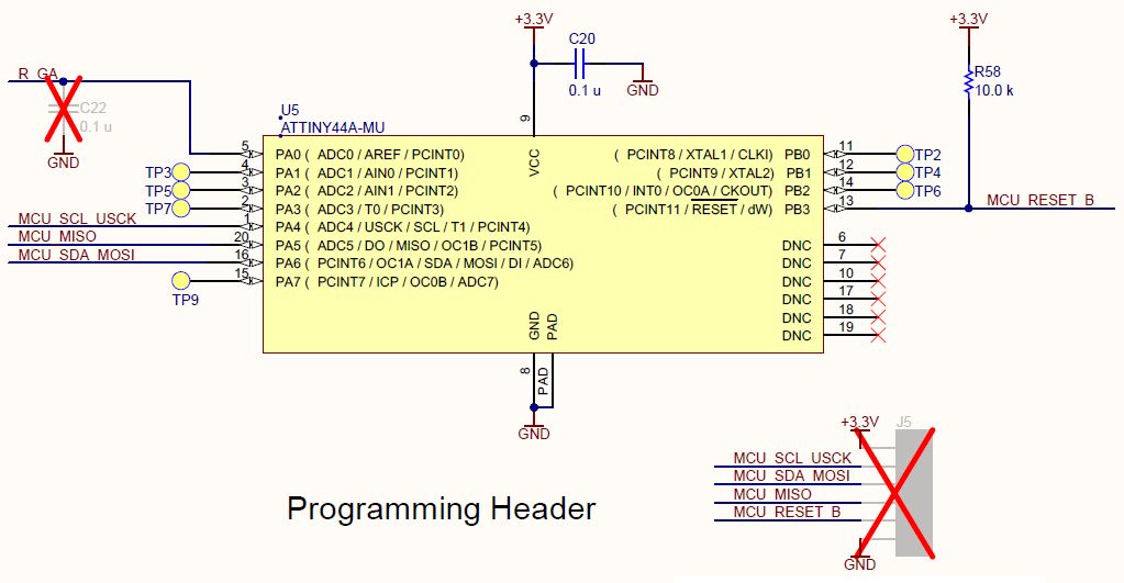
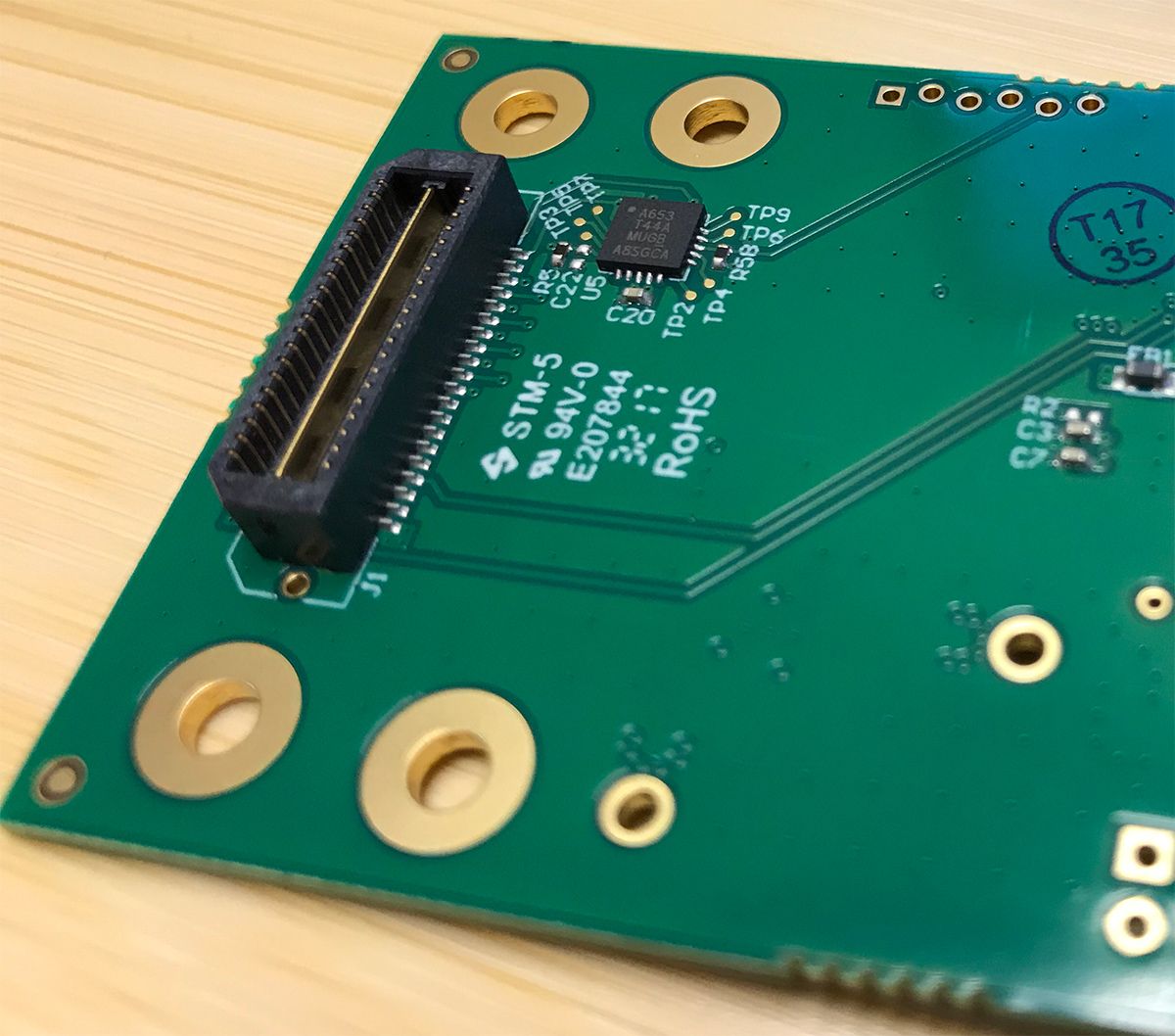
Schematic and Layout
Below are the schematic and layout of the ATTINY44A-MU on our DAC peripheral. The schematic is simple and easy to replicate. The layout is also simple and compact. The programming header is the staggered pin arrangement at the top right of the board photo. This arrangement allows a header to be inserted temporarily without actually mounting a socket to the board for programming.
You can download the full specification and read more about SYZYGY on SYZYGYfpga.io. The DNA Specification has also been posted here.