Project update 4 of 7
[Video] How PowerEver Works, Part 2
by Dr. KluiIn the last update we touched on the basic principles of the PowerEver. In this second part we will go into deeper detail.
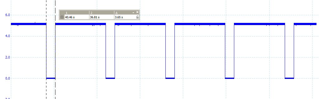
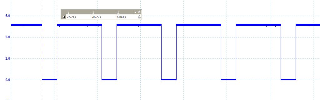
Fig. 1
Fig. 1 is our reference signal borrowed from our last update, which shows a signal captured from output pin 3 at the heart of PowerEver’s ATTiny13A controller. If this pin is high, around 5 V, no current will be drawn at all (except a few milliamps from the on-board LED and the MCU itself). When the signal goes low a current of about 100 mA will be drawn briefly (3.65 sec as seem in the chart) by the PowerEver circuit through two 91 Ohm resistors. This action repeats about every 24 sec in order to counter the automatic turn-off algorithm of power banks.
Fig. 2
Fig. 2 is the waveform after triggering the push button switch on the back side 10 times. After doing this, the pulse width becomes wider (6.04 s instead of 3.65 s) as you can see, meaning that the PowerEver is drawing more current as compared to its default factory setting.
This feature is necessary because every power bank manufacturer uses a different auto shut-down detection algorithm (typically between 10 to 30 seconds after no/small load connected). If your power bank shuts down with the PowerEver connected, simply triggering the button one or more times will allow the power bank to stay permanently on.
If we divide the pulse width with the fixed period of 24 s we will obtain 15% and 25% duty cycles correspondingly. Each time you short press the button the PowerEver will add 1% duty cycle. For the opposite action simply perform a long press. Timing periods of 20-25 s with 8-17% duty cycles (8-17 mA current drainage) are optimal for a large number of the power banks I have tested.
PowerEver is a noise filter

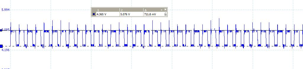
Nope, I’m not joking. The figures above (fig. 3 & 4) show you a difference in noise level on the +5V USB jack on the power bank side before and after using it with a LED strip driven through a constant current driver. The voltage ripples were reduced from 1.28 V to 0.71 V with and without connecting through the PowerEver. {signal5}
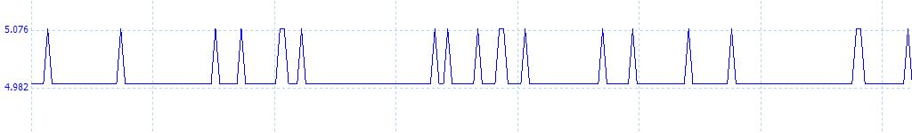
Fig 5 & 6 again show a noise density comparison at the power supply line of the wireless guitar receiver in an effects pedalboard.
Obviously, powering the receiver through the PowerEver helps with reducing the high frequency noise density. This is thanks to a ceramic capacitor on the PowerEver in combination with integral resistance along the power cord that acts as low-pass filter for the high frequency noises generated by most LED constant current drivers and switch-mode power supplies.
PowerEver and a pedalboard
How does it sound to use PowerEver with the wireless unit on my pedalboard? Check this out (fun fact, the person playing is my daughter!):
Do you need your own version of PowerEver?
If you are a programmer and would like to make your own specific version of PowerEver, then this is the best place to start.
Thank you Kadamski for pointing out a way to further decrease self-drawn current.
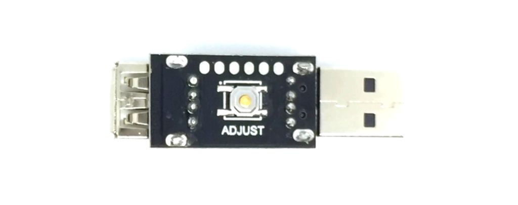
To program you need an AVR programmer to attach to the pads (from left to right) 5V, GND, Reset, SCK, SDO, SDI and flash the .hex file compiled from source in the GitHub repository. Also you can find the latest updates, when available, on the same GitHub link.
Thank you,
Dr. Klui
Imagine | Invent | Innovate