Project update 6 of 22
Arrange LED Strips into a Video LED Display
by Gordan GThrough communication with our Crowd Supply backers and visitors of our website, we have learned that some of you are not so familiar with the operation of LED strips. That’s why we want to give you more information and explain how the LED strips are easy to use with the right LED controller.
The current Pixblasters MS1 Video LED Controller version supports WS2811, WS2812, WS2812B and SK6812 RGB LEDs. In the future, we plan to add more control functions, like support for the APA102 LED strips. Adding new features to field deployed Pixblasters controllers is already possible and very easy.
We will distribute new configuration files with the upgraded features sets and the Pixblasters users will update the controller through a simple procedure that does not require special tools or knowledge. Just connect the Pixblasters controller to the PC via a serial USB cable, use on-board DIP switches to select the firmware flasher FPGA configuration and follow the procedure similar to the one described in our campaign update Define the Monitor Image Window to Show on Your Video LED Display.
The on board memory for FPGA configuration files enables storage of 8 different FPGA configurations. There are five free memory blocks reserved for additional FPGA configurations, since the memory currently stores firmware flasher, LED master and LED slave FPGA configurations.
Our preferred LED strip model is WS2812B (Figure 1) because it enables the fastest LED operation, and combined with the Pixblasters MS1 video LED controller, full 60 frames per second (fps) video refresh rate. This is much faster than it is possible with the majority of competing controllers and enables smooth video reproduction regardless of the LED display’s size.
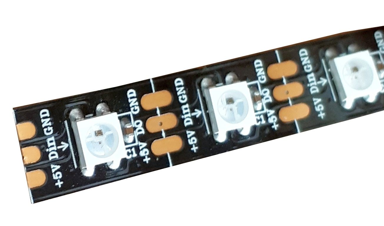
The WS2812B RGB LED strips have the 3-pin interface: +5V power input, GND ground pin, and the DIN control data input. Note the small arrow sign on the LED strip. It shows the data flow direction and it must be respected at all times, or the LED strip will not light. The LED strip must be always connected to the Pixblasters video controller with the arrow pointing away from the board’s digital output.
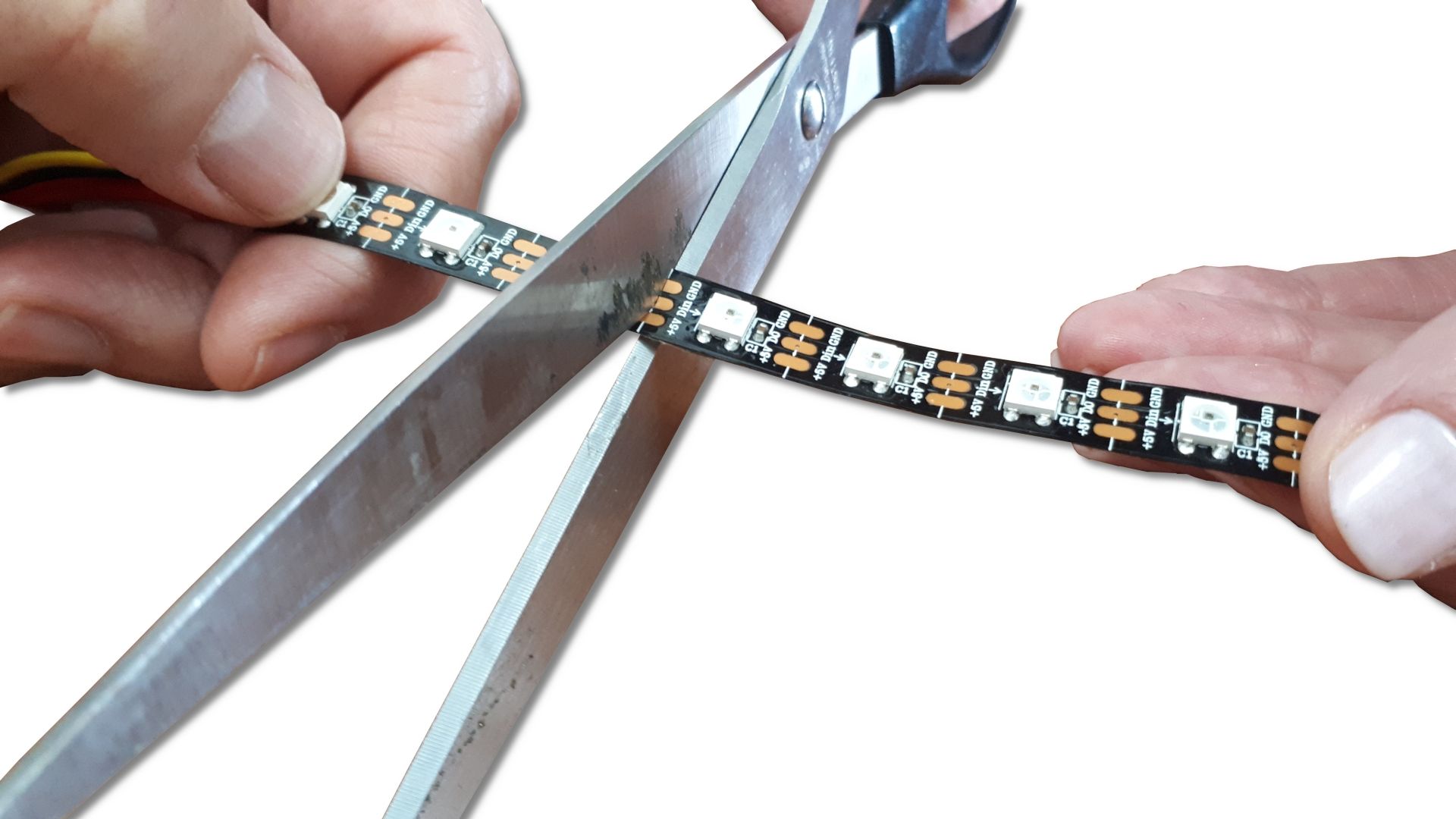
The Figure 2 shows a versatile LED video display formatting tool – the scissors. Use it to cut the video display line to the requested length. The WS2812B LED strip can be cut between any two LEDs. The cutting positions for some other strips can be less flexible, i.e. some can be cut behind groups of three LEDs.
Through our campaign, we often say that the LED strips can be used without soldering. While being skilled with the soldering iron is definitely helpful, one can use the locking connectors, like the one shown on the Figure 3, to connect the wire leads to the strip without soldering. The wire leads with the removed isolation simply insert into the Pixblasters controller’s high-quality snap-action connectors. This way, the reliable contact between the strip and the controller can be established without soldering.
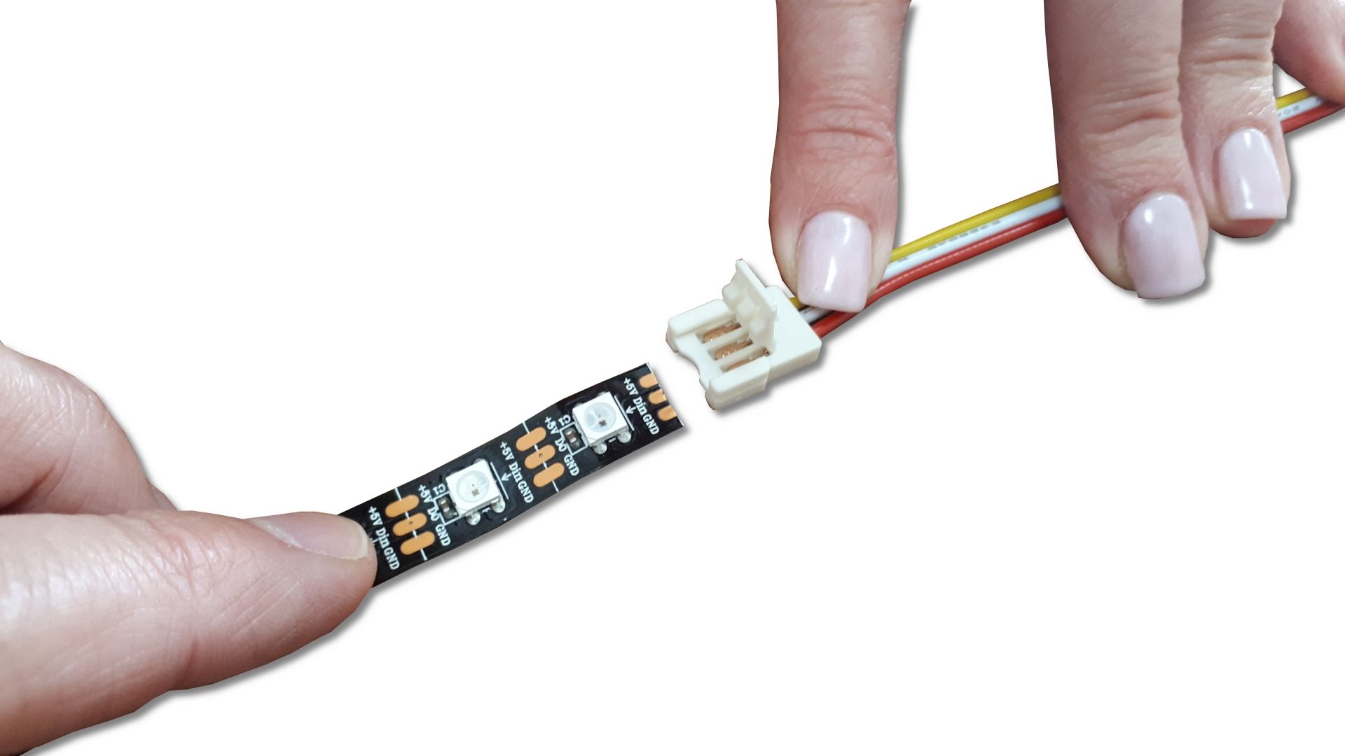
Besides the connector type shown on Figure 3, there are different types locking connectors that connect two pieces of the LED strip.
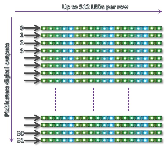
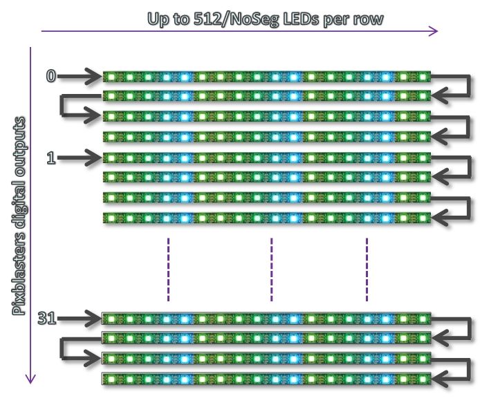
LED strips can be arranged in LED display’s matrix driven by the Pixblasters controller in two main ways. The Figure 4 shows the LED strips arrangement without strip segmentation. Each of 32 Pixblasters MS1 controller outputs drives a display line of maximally 512 pixels.
Figure 5 shows the LED strips arrangement with the line segmentation, which enables more flexibility in display’s resolution setup. Each Pixblasters MS1 controller’s digital output can drive max. 512 pixels, but those pixels can be arranged in multiple display lines. The figure 5 example shows 4 lines driven by a single Pixblasters digital output and this arrangement enables the maximum resolution 128 x 128 (Horizontal x Vertical) pixels.
The Pixblasters controller needs to be configured, through the configuration menus, for such LED matrix arrangement and the further display control is fully automatic. There is no need for any input image manipulation.
The LED matrix with the embedded segmentation requires a bit different LED strips wiring and it is absolutely necessary to take care on the data flow direction. Take for example the four horizontal lines controlled by the digital output 0 from the Figure 5 example. The first LED strip segment must have the data arrow (Figure 1) pointing from left to right, the second LED segment must have the data arrow pointing from right to left, the third one from left to right, and the fourth from right to left. Such LED arrangements assures an uninterrupted serial data flow.
Because of the significant power requirements, the LED strips need to be powered by an external regulated power supply. Each RGB LED draws approximately 50 mA when it is set to full brightness white color and powered at VDD = +5V, so make sure to select the proper power supply. Pixblasters MicroSign demo display uses the 350W (60A) AC/DC converter, which makes the LED matrix of 1,920 LEDs demo display (max. 96A) a bit underpowered. However, as long as the display shows changing and colorful video content, the power supply is fully sufficient.
Controlling of large numbers of LEDs requires high-performance controller, able to feed each LED with individual control data while keeping all timings stable and within pretty precise and narrow limits. Each WS2812B RGB LED takes the 24-bit control data and the single bit timing tolerance is typically +/- 150 ns. Beyond a certain number of connected RGB LEDs, the software LED controllers cannot cope with such timing requirements and the displays cannot function. The Pixblasters controller with its customized FPGA based LED driving controller keeps the absolute precise timings regardless of the number of the attached LEDs!