Project update 4 of 9
Campaign Ending Soon and Other News
Hello everybody. There are a couple of updates this week, but first I want to thank everyone who has supported the campaign thus far. We have a few days left in the campaign, so please help spread the word and support JuicyBoard over the campaign’s final days. We couldn’t do this without you!
R1000AX Ready to Gerber Out
We’ve finalized and revised Gerber files for R1000AX, R1001, R1002, R1003, R1005, R1007 and we’re ready to send them out for manufacturing on Monday. The R1000AX design includes the latest modifications that provide accommodation for compute modules. We will keep you updated with manufacturing and test milestones.
Introducing R1001 Bonding
Since we started designing JuicyBoard, we’ve been thinking of a better way to synchronize multiple stepper motors. There are certain designs which involve driving more than one stepper motor simultaneously. A popular case is the RepRap Prusa i3 3D printer where the Z-axis is actuated by two stepper motors moving together in sync. A common implementation is to wire the motors in parallel and drive them by a single chip. The main problem with this configuration is that no matter what (even with identical motor models) there will always be a mismatch in motor coil characteristics, this causes an imbalance in current distribution, which in turn causes a significant imbalance in torque between the motors. You can probably see cases where one motor is rotating while the other is stalled. If you try wiring more than two motors in parallel the imbalance becomes much worse.
To address this problem, we’ve designed R1001 in a way that allows multiple modules to be synchronized at the hardware level, where the delay between step/dir/en signals over these modules is on the order of nanoseconds (which is practically zero when actuating motors). To do this, you need to determine a master driver which JuicyBoard controls and place a special jumper PCB that makes the next R1001 module a slave.
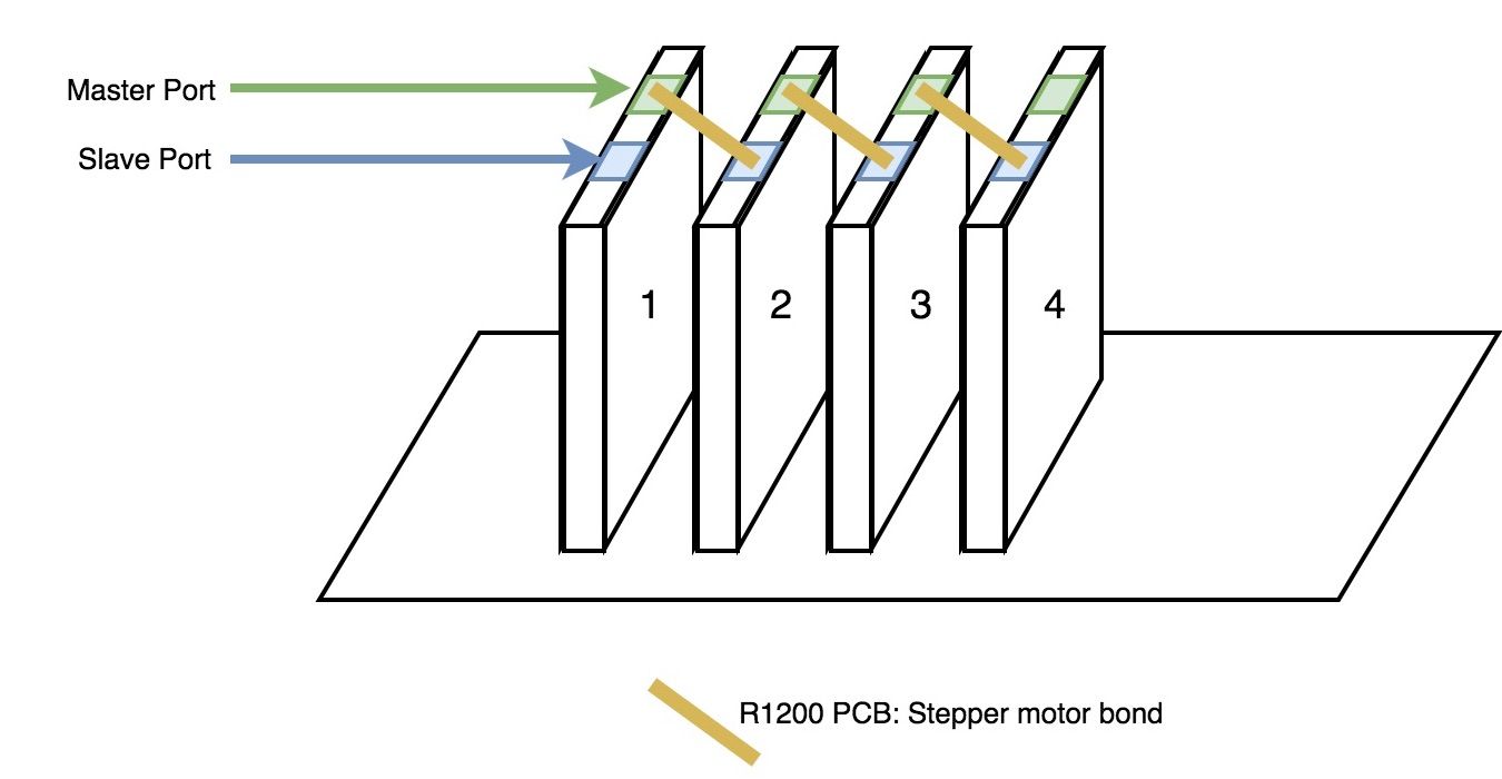
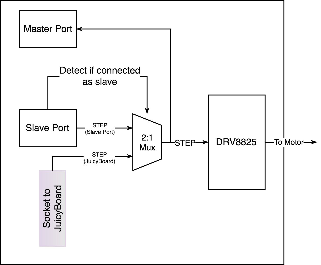
The following figure explains a block diagram of how bonding works inside R1001:
This video demonstrates 2x R1001 drivers synchronized, JuicyBoard is only driving STEP/DIR signals of the master board.