Project update 7 of 12
Digital GPIO & Comparison to Moku:Lab
by Dejan PriversekScopeFun provides 12 digital General Purpose Input/Output (GPIO) pins. These digital channels – which can serve either as inputs or as outputs – are useful for a wide range of applications. You can control them directly through the ScopeFun software or by way of a Python script. ScopeFun includes two instruments that make use of the GPIO: the logic analyzer and the digital pattern generator. For this update, we have created a short tutorial that demonstrates both applications.
Digital Pattern Generator
A digital pattern generator is a device that generates user defined digital signals. It can output a sequence of logic HIGH and LOW pulses that can be used to test and verify digital circuits and devices such as embedded systems, digital state machines, digital-to-analog converters, microcontrollers, and FPGAs. In the following tutorial, we will use the digital pattern generator to output a custom digital sequence and simultaneously observe that sequence with the logic analyzer.
Setup
First we will define the digital sequence in a file. The samples in this file are JSON formatted text, such as:
{
    "digitalChannel0" : [0,1,0,1,1,1,1,1,1,0,0,1,1,...
    "digitalChannel1" : [1,0,1,0,0,0,0,1,0,0,0,1,1,...
    "digitalChannel2" : [0,0,1,1,1,0,1,1,1,1,0,1,1,...
    ...
}
After creating the file, we can upload it to the FPGA. The upload function is on the Digital Setup tab of the ScopeFun software. This tab also allows us to adjust the output HIGH voltage (from 1.25 V to 3.3 V) and set the output frequency of the pattern generator.
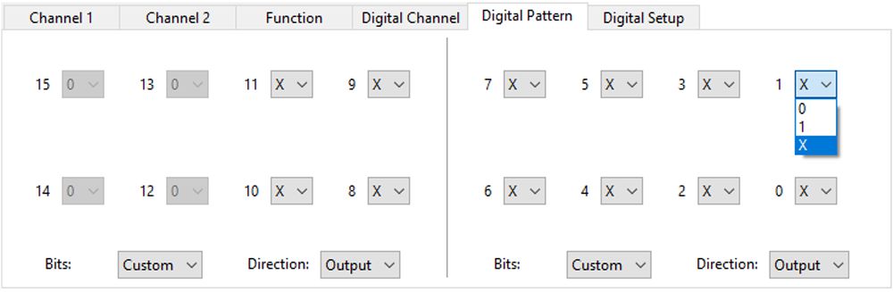
{scopefun-digital-setup} We can use the Digital Pattern tab to configure the digital GPIO interface. For each channel, we will set the signal direction to OUT and the value to X. This will instruct ScopeFun to output the pattern from the uploaded file. If we want to override one or more channels with a logic HIGH or LOW, we can set the value(s) to 1 or 0, respectively.
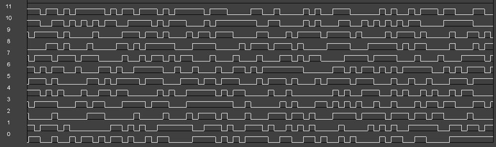
Although we have configured all 12 digital GPIOs as outputs, we can still use the logic analyzer to monitor the sequence generated by the file we uploaded. This is possible because inputs to the logic analyzer are connected, within the FPGA, to the digital pattern generator. When the digital pattern generator is not used, the logic analyzer inputs can be used to monitor the GPIO pins.
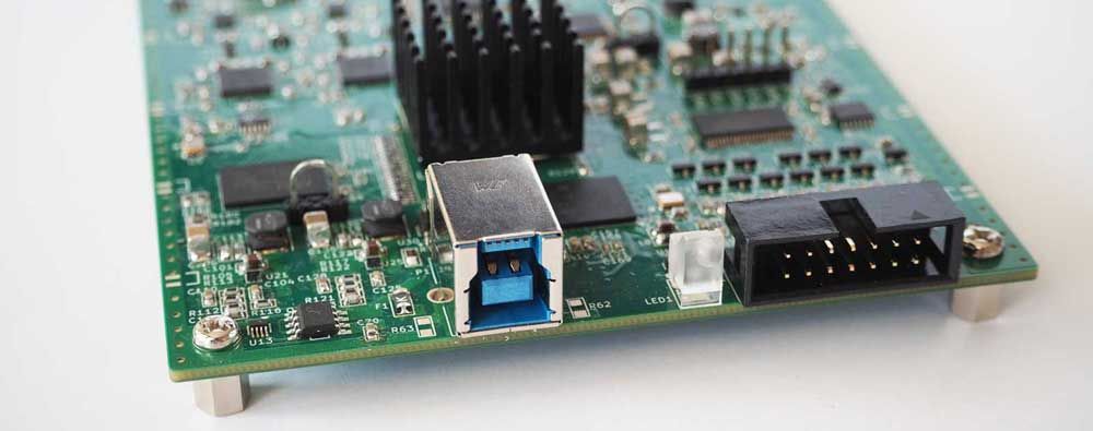
To verify the output of our digital pattern generator, we attached some LEDs to the GPIO pins:
ScopeFun’s digital GPIO interface allows us to connect to the digital world in various ways, and it has already given us a number of ideas for additional tools that we would like to build in the future. We could add some predefined signals to the digital pattern generator, for example, such as counters or BER testing sequences. We could also integrate sigrok protocol decoders into ScopeFun’s logic analyzer. Doing so would greatly simplify protocol decoding. Reading and writing EEPROMs through the GPIO pins might be another interesting application.
Comparison with the Moku:Lab instrumentation platform
Some of you have requested more information about how ScopeFun compares to other high-end, all-in-one instrumentation platforms. For this update, we put together a comparison with Moku:Lab:
| ScopeFun | Moku:Lab | |
|---|---|---|
| Price | $650 | $4990 |
| Open Source | ||
| Firmware/Software | Yes | No |
| Hardware | Yes | No |
| Primary Components | ||
| FPGA | Xilinx Artix-7 XC7A35T | (not specified) |
| Connectivity | USB 3.0, IP with server app | USB 2.0, IP, WiFi |
| Power supply | USB powered | External power supply (100 to 240 V, 50/60 Hz) |
| RAM | 512 MB DDR3 | (not specified) |
| Supported Instruments | ||
| AWG | Yes | Yes |
| Data Logger | No* | Yes |
| Digital Filter box | No* | Yes |
| Digital Pattern Generator | Yes | No |
| FIR Filter Builder | No* | Yes |
| Bode Analyzer | Yes | Yes |
| Laser Lock Box | No* | Yes |
| Lock-In Amplifier | No* | Yes |
| Logic Analyzer | Yes | No |
| Oscilloscope | Yes | Yes |
| Phasemeter | No* | Yes |
| PID Controller | No* | Yes |
| Spectrum Analyzer | Yes | Yes |
| Waveform Generator | Yes | Yes |
| Oscilloscope | ||
| Channels | 2 | 2 |
| Analog BW | 100 Mhz | 200 Mhz |
| Max. Sampling Speed (Real-time) | 500 Msps | 500 Msps |
| Equivalent Time Sampling | Yes (2.0 Gsps) | No |
| Memory Depth | 128M | 16k |
| Resolution | 10-bit | 12-bit(13-bit at 125 Msps) |
| Input Voltage Ranges | ± 10 V, ± 5 V, ± 2.5 V, ± 1 V, ± 0.5 V, ± 0.25 V, ± 0.1 V, ± 0.05 V | ±5 V |
| Min. Voltage Sensitivity | 0.098 mV | 2.441 mV (1.222 mV at 125 Msps) |
| Input Coupling | AC, DC, GND | AC, DC |
| Arbitrary Waveform Generator | ||
| Channels | 2 | 2 |
| Max. Update Rate | 200 Msps | 1.0 Gsps |
| Resolution | 12-bit | 16-bit |
| Output Range | ±2 V | ±2 V |
| Custom Signal Data Points | 32k | 8k (65k at 125 Msps) |
| Logic Analyzer | ||
| Channels | 12** | - |
| Sampling Speed | 250 MSps | - |
| Memory Depth | 128M | - |
| Digital Outputs (GPIO) | ||
| Channels | 12** | - |
| Digital Pattern Generator | Yes | - |
| Digital Pattern Generator Buffer Size | 32k | - |
| Update Rate | 250 MSps | - |
* Could be implemented through future firmware and software upgrades
** Digital channels share the same I/O pins