Project update 3 of 12
Hacking ScopeFun
Hacking ScopeFun
One of the main advantages of open hardware is that it gives users the chance to understand exactly how it works. But open source designs also have the benefit of being more extensible. Because ScopeFun is completely open source, users can modify it or add new features simply by editing the source code.
To show how easy it is to customize ScopeFun, we have created a short tutorial. For the purpose of this tutorial we have implemented an averaging filter, inside the FPGA, that averages digital samples coming from the onboard AD converter. As we learned in our previous update, this has the effect of reducing noise in the captured signal.
Before we start hacking, lets review the main aspects of the ScopeFun design.
ScopeFun Architecture
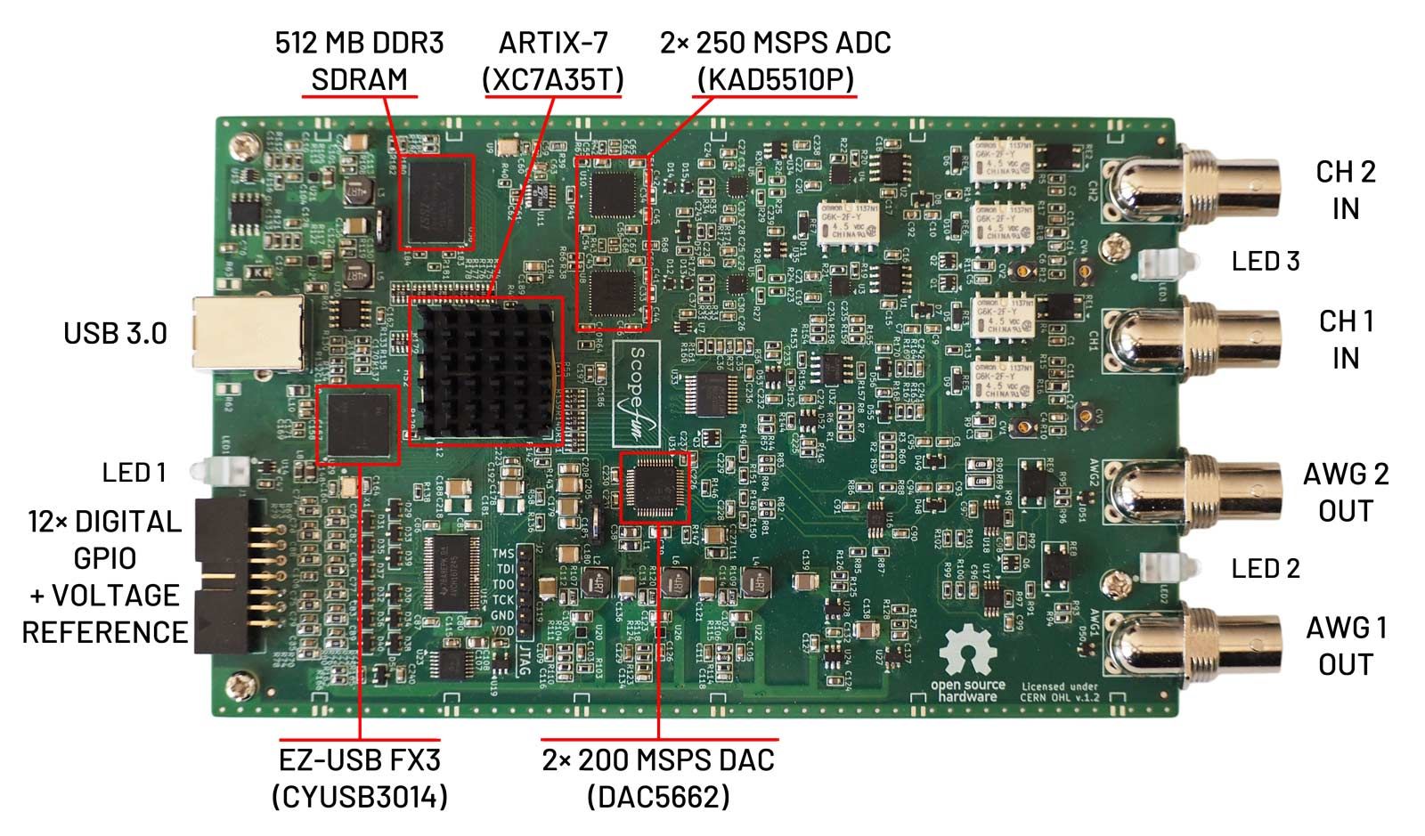
Hardware
ScopeFun hardware provides the following interfaces and components:
- 2 analog inputs (sampled through KAD5510P)
- 2 analog outputs (generated through DAC5662)
- 12 digital GPIO's + GPIO reference voltage output
- 3 LED's to indicate operation
- Xilinx Artix-7 FPGA (XC7A35T)
- 512 MB DDR3 SDRAM
- USB 3.0 controller Cypress EZ-USB FX3 (CYUSB3014)
Firmware
All the main hardware components are connected to the Artix-7 FPGA, which handles several tasks:
- Reads hardware control registers and configures connected hardware components
- Reads samples from AD converters and digital inputs
- Processes samples and detects trigger events
- Saves samples to DDR3 RAM depending on the trigger settings
- Reads samples from DDR3 RAM and transfers them to an FX3 USB controller
- Reads custom waveform samples for analog and digital generators
- Generates signals for analog waveform generators
- Generates signals for digital pattern generator
- Controls GPIO interface voltage
- Controls analog front-end (gain, offset, and coupling)
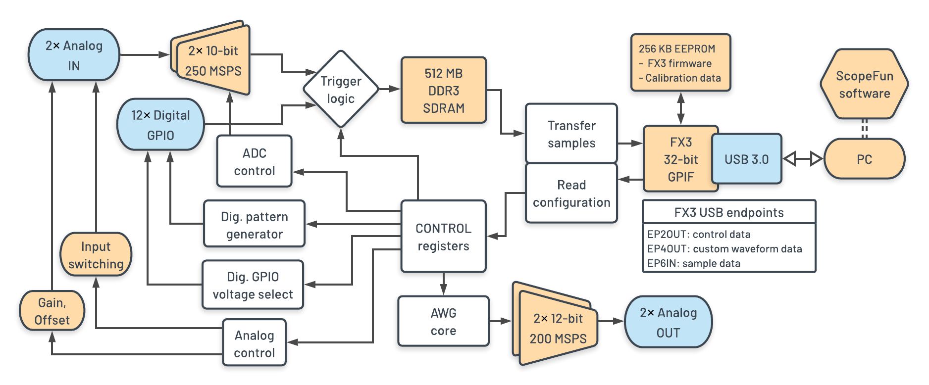
The FPGA is designed to process these tasks in parallel. This maximizes throughput and allows for independent operation of different design blocks. The oscilloscope, arbitrary waveform generators, and digital pattern generator can all work independently.
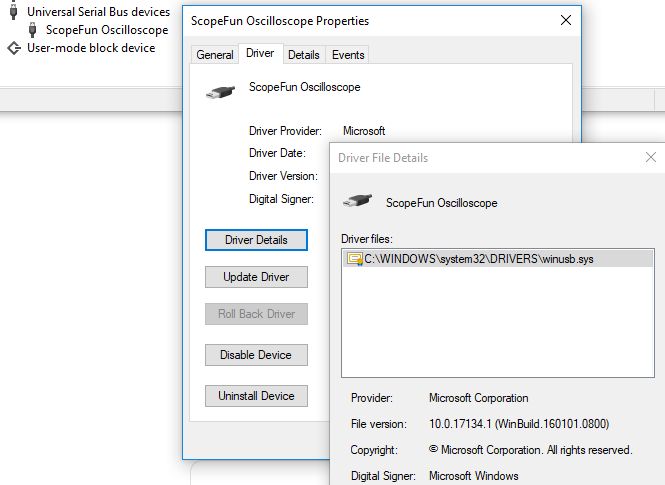
The main task of the FX3 firmware is to handle USB transfers between the FPGA and the PC. It provides this "bridge" through it’s DMA channels and its GPIF interface, which supports fast data transfer rates. The FX3 firmware also allows the FPGA and onboard EEPROM to be programmed through USB. The EEPROM is used to store the FX3 firmware and ScopeFun calibration data. This allows ScopeFun hardware to be used on different computers without the need to re-calibrate it. Another useful feature of the FX3 firmware is its support for Windows OS descriptors. This allows Windows to identify the drivers it needs when ScopeFun is first connected to a particular computer. This is possible because ScopeFun uses a standard USB driver, WinUSB, which is already included with Windows.
Software
All of the hardware settings are configured in software and reflected back to hardware control registers. Each time a setting is changed, control data is sent from the software to the FPGA through the FX3’s EP2OUT USB endpoint, which is configured in the FX3 firmware. When the FX3 receives this data, it immediately asserts the GPIF flag "flagA", which informs the FPGA that new configuration data is available. This allows for instant changes in hardware configuration. In a similar way, custom waveform data is sent from the software to the FPGA through the FX3’s EP4OUT endpoint. In the other direction, data captured from ScopeFun inputs is sent through the FX3’s EP6IN endpoint to the software.
Implementation of the Averaging Function
We have seen, above, that ScopeFun’s hardware is controlled by data stored in its control registers. So if we want to give users control over the feature we are about to add, we will need to expand our set of registers. The new register will tell the FGPA to enable or disable our new averaging function. For reference, a list of all hardware control registers can be found on our Gitlab repository.
Averaging ADC Samples
As mentioned earlier, we will implement our averaging function in the FPGA. This function will take ADC samples as input and calculate a mean value for the last eight samples received. This will happen every ADC clock period (250 MHz), which will produce a continuous signal on the output of the averaging function. The FPGA source code for the averaging function is available on our Gitlab repository.
Controlling the Hardware
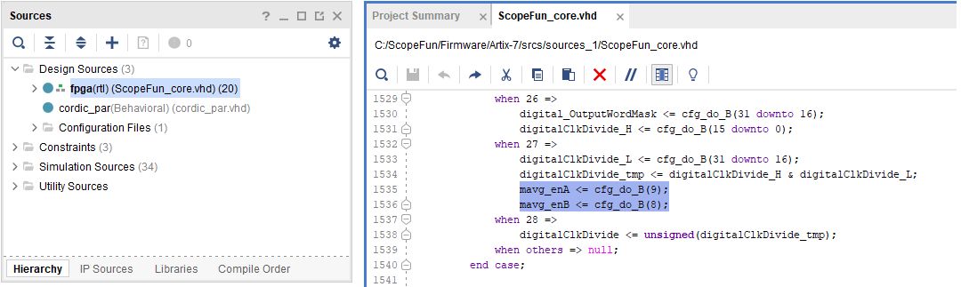
Now that we have implemented the averaging function, we need to give users a way to control it. The averaging function will be enabled if the controlling bit is asserted in the software and disabled if it is not. The following VHDL code snippet shows how the FPGA reads the contents of control registers in the main ScopeFun process.
Now that everything is ready on the firmware side, we just need software to control our new feature. To do so, we will add a checkbox that can be used to to enable and disable the hardware averaging function. We can do so easily with a tool called vxFormBuilder, which generates the necessary UI and callback code:
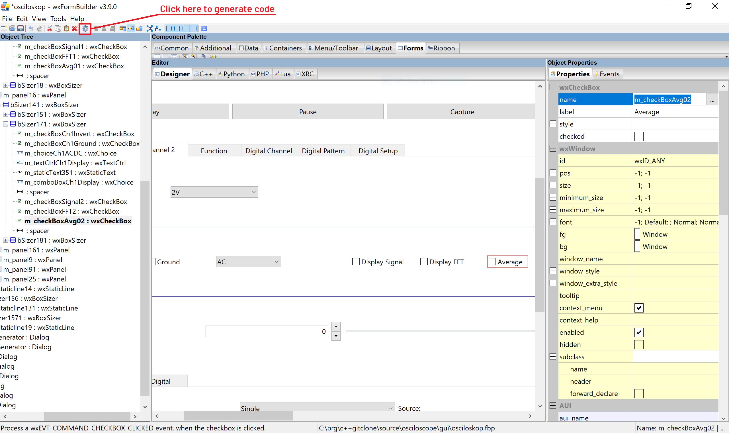
In the screenshot below, we have added the new control register:
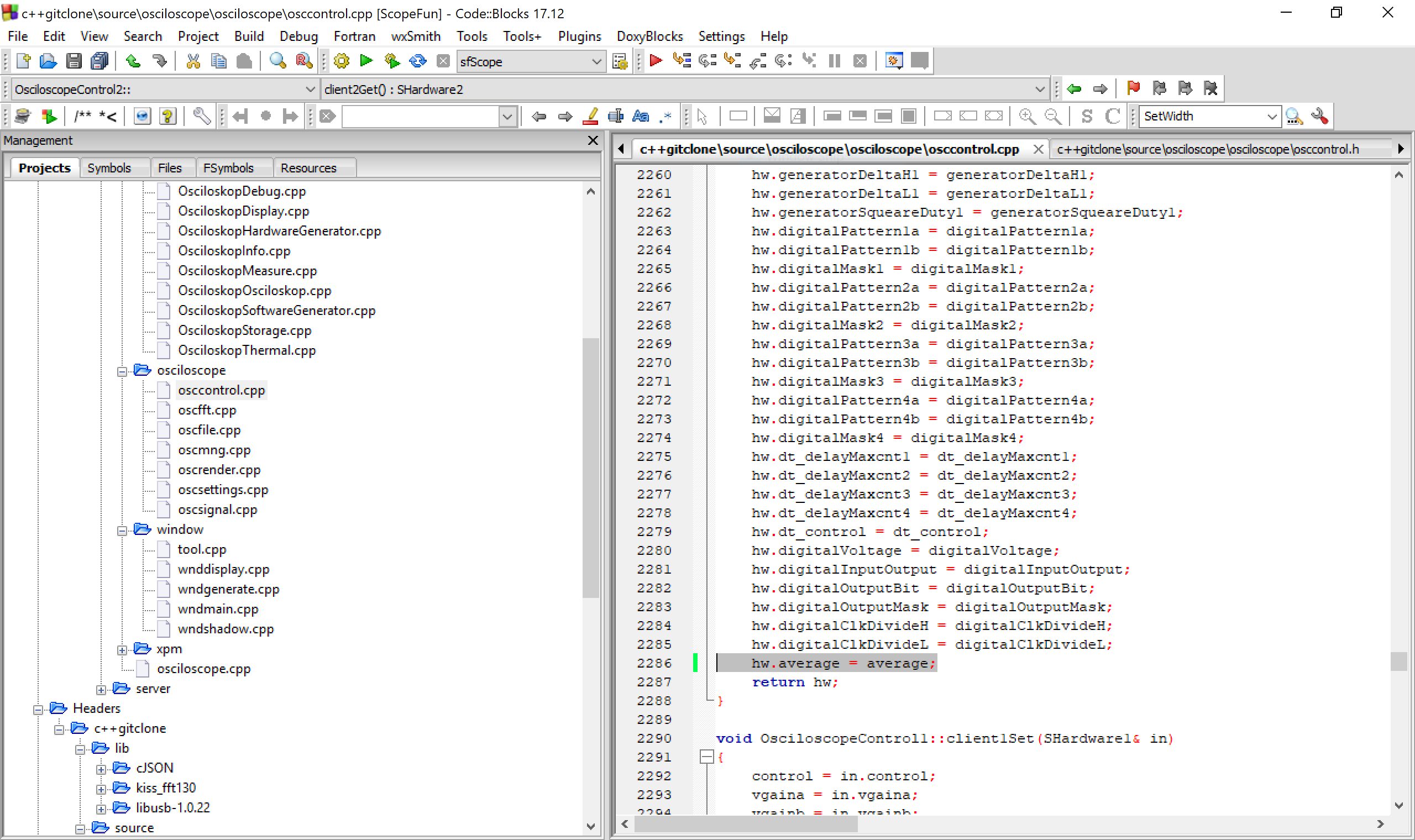
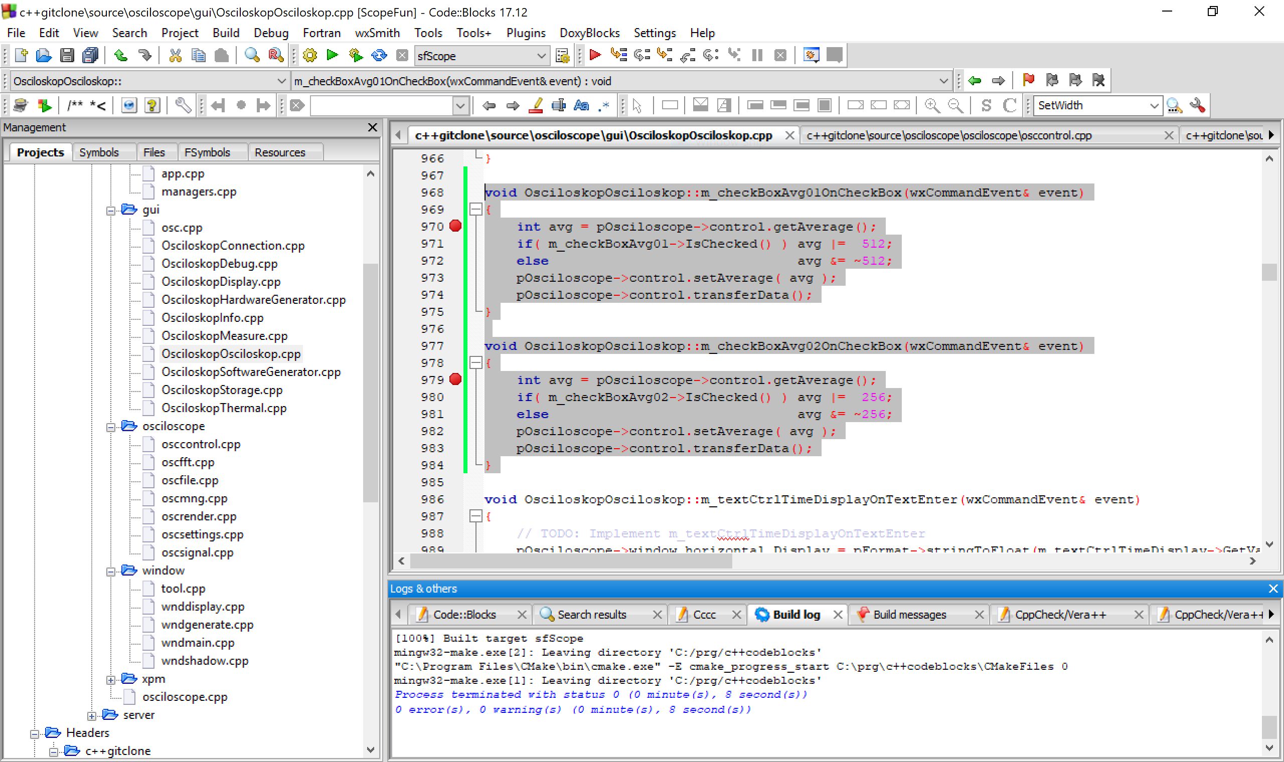
Then we implemented a function that asserts the register values depending on the value of the checkbox:
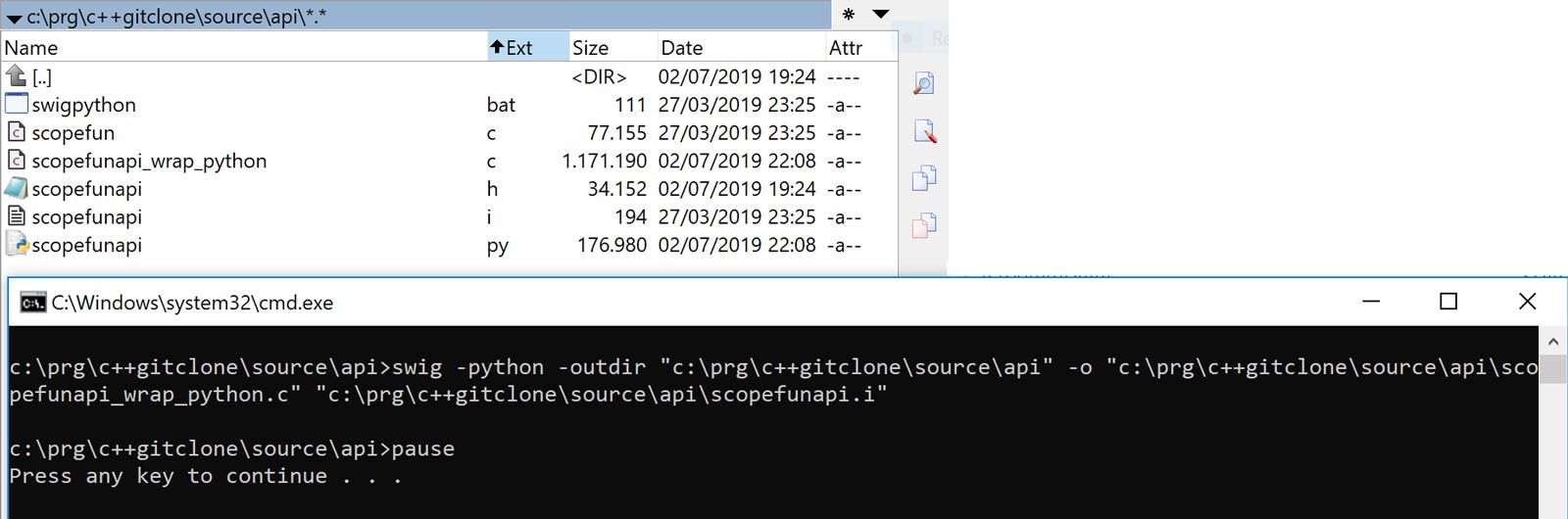
In the final step, we update the Python API wrapper so that our new register can also be controlled by a script. For this purpose we simply run the swigpython.bat script, which generates an updated API.
Note: The source code that implements this averaging function is available on our Gitlab repository, and compiled binaries are available on our homepage.
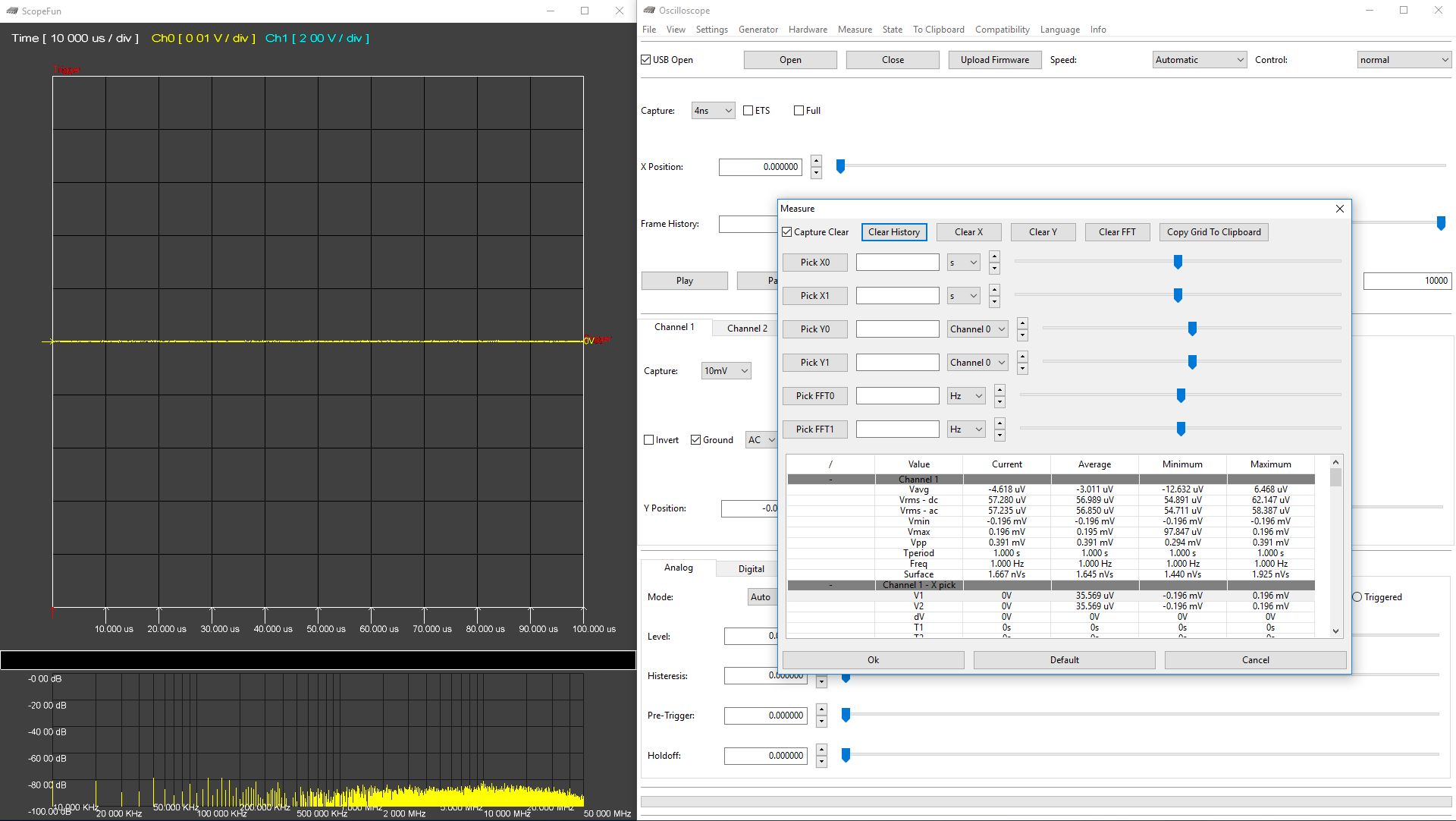
Measurements
The purpose of our averaging filter is to reduce noise, so let’s see how it performs. To do so, we have taken baseline noise measurements on the lowest vertical scale setting, which is the noisiest:
| Range | Noise RMS-AC (Without Averaging) | Noise RMS-AC (With Averaging) |
|---|---|---|
| 10 mv/div | 0.099 mV | 0.058 mV |
Conclusion
We have learned about the ScopeFun’s architecture and demonstrated a simple process by which we can extend its set of features. As expected, we have seen an improvement in the level of baseline noise after enabling our new averaging filter. We believe this level of flexibility will greatly benefit engineers, developers, electronics enthusiasts, and other members of our community.