Through the past several updates, I shared details about the design, development, and testing of Tigard. For this update, we’ll focus a bit deeper on a single feature - the SWD/I2C mode switch.
Obstacles and Workarounds
The FT2232H is an extremely versatile device. It has a robust USB interface that can efficiently get data out to output pins and stream data in from its input pins, which makes it a good choice for lots of devices. One thing that can complicate this are protocols that have bidirectional data pins - FTDI’s "Multi-Protocol Synchronous Serial Engine" (MPSSE) defines specific pins to be input pins and output pins and can’t easily switch them on the fly. The solution is to connect both an input and an output pin to these bidirectional signals.
SWD
Serial Wire Debug or SWD is an alternative to the standard JTAG pins that only requires two signals - SWCLK, and the bidirectional SWDIO. OpenOCD’s documentation describes how to do this electrically: an input pin on the FT2232H’s is connected directly to SWDIO, while an output pin connected via a resistor. This works because when the target device is speaking on the SWDIO line, the resistor prevents the FT2232H output from interfering.
I2C
I2C is specifically addressed in an application note from FTDI: Interfacing FT2232H Hi-Speed Devices to I2C Bus The application note recommends connecting both the FT2232H input and output pins directly to the SDA signal, and using code to disable output while receiving input. It also points out that both SDA and SCL need pullup resistors, however in our experience they are almost always present on the target boards and rarely necessary.
Fundamentally the FT2232H is not well suited for I2C, and there’s nothing Tigard can do to change that, so our design decision was to make a ‘best effort’ to enable I2C as best we could without sacrificing any other interfaces.
Switches and Headers
I2C and SWD support affects the wiring of several connectors. In addition to connecting the data in and data out pins, there are a few other changes that make the headers more useful:
I2C header
This header was a late addition and is the only single-purpose header on the board. It only works when in I2C mode, and is just designed to work with STEMMA QT and Qwiic devices (plus others with adapters). Since we had the available space, we chose to add this connector since it makes working with these devices much easier.
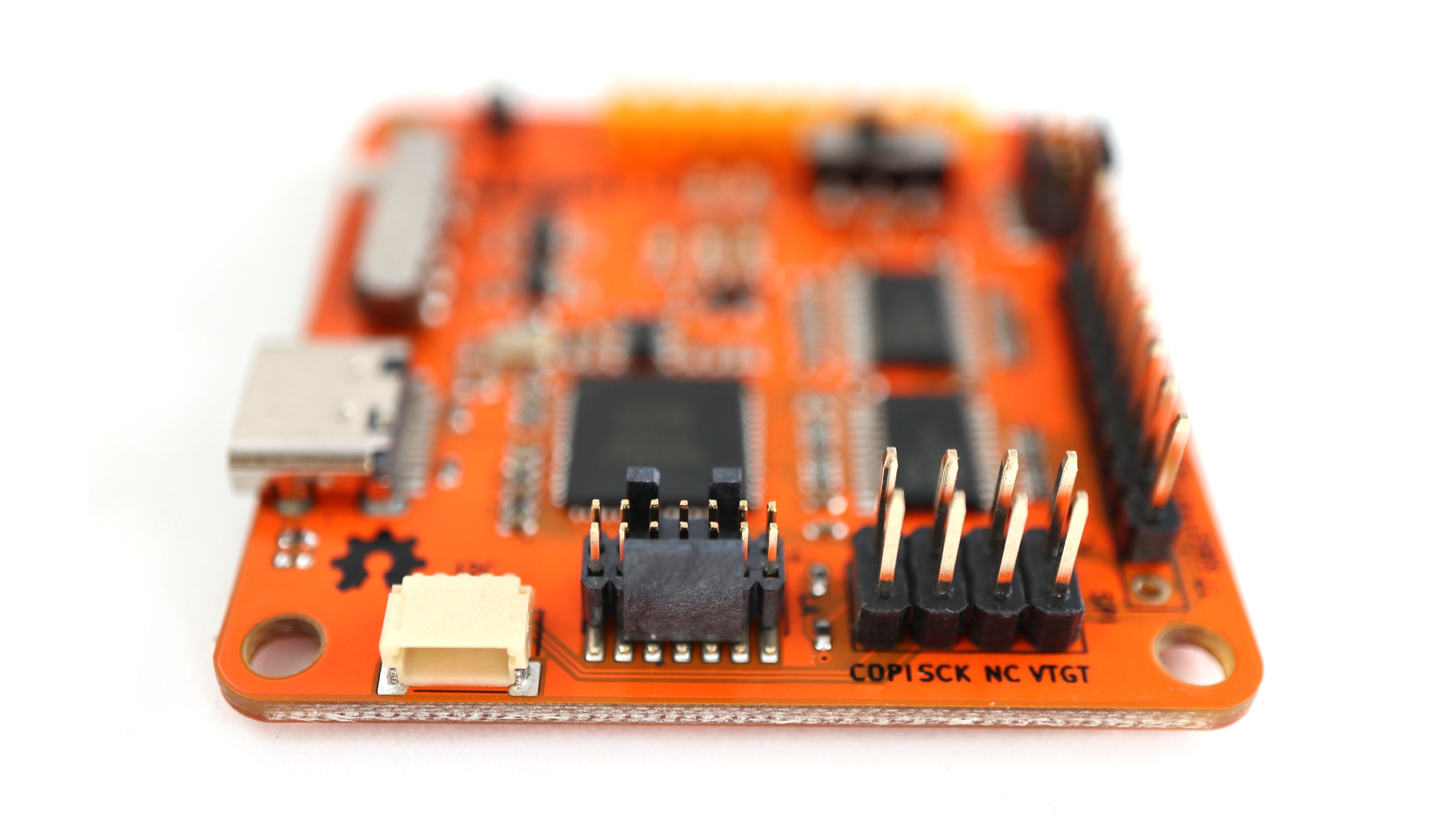
SPI/I2C 2x4 Header
This header is laid out to match the pinouts of many 8-pin SPI and I2C devices, making it easy to use with a ribbon cable, chip clip, or socket. Conveniently, VCC, GND, SCK/SCL, and COPI/SDA are in the same places for both protocols, but some I2C devices use pin 2 as an address pin, so leaving CIPO attached in I2C mode could cause problems. We were aware of this but decided that since 1) I2C is only best effort, 2) You may be able to disconnect that pin on the wire or target, and 3) we also have a dedicated I2C header, it was not as important as other features.
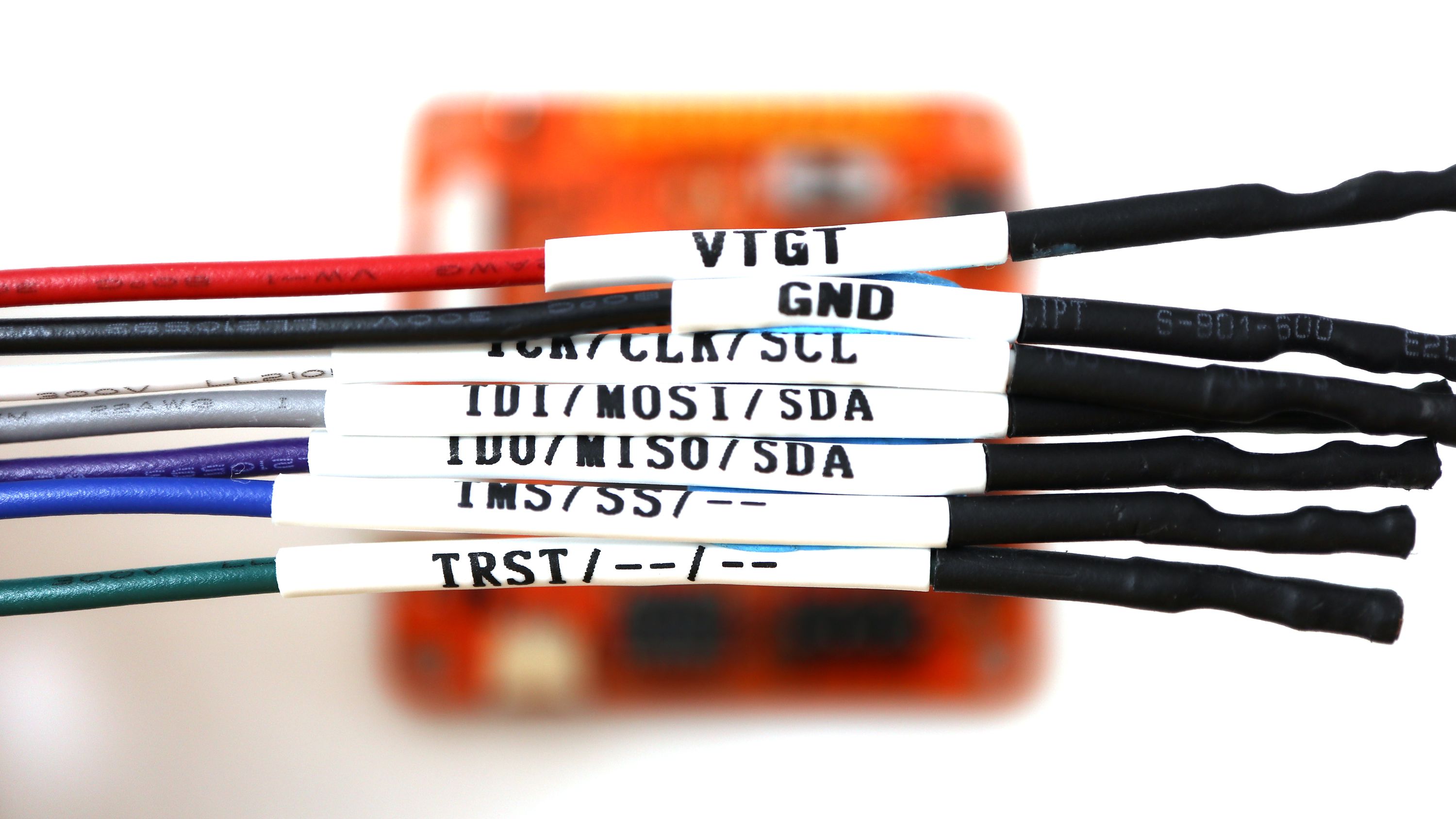
JTAG Header and labeled harness
This is the ‘all purpose’ header because it has a labeled wiring harness. The wire labelled TDO/CIPO is the best choice to use as an SDA or SWDIO signal, though in many cases the TDI/COPI wire will work as well.
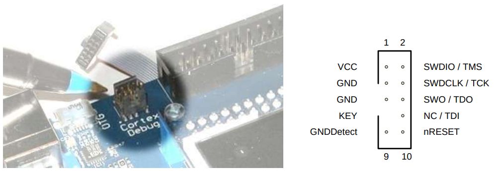
CORTEX Header
JP2 HACK
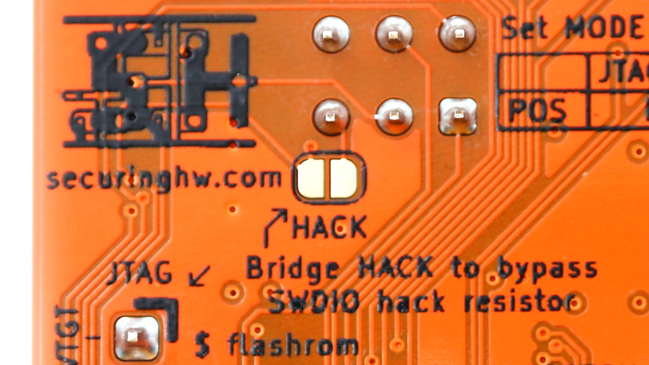
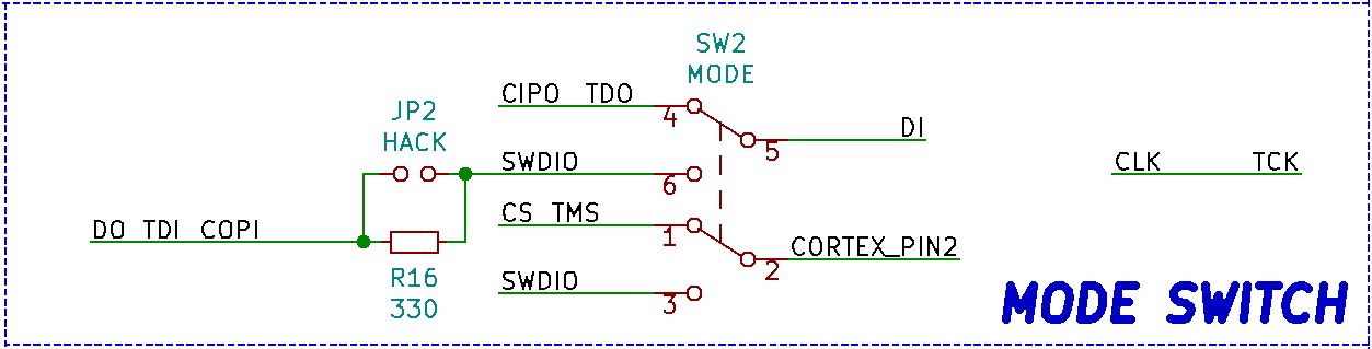
We chose a 330 ohm resistor which worked in our testing for both SWD and I2C modes. In case there’s a scenario that really needs input and output tied together without a resistor, there’s a solder jumper labeled HACK on the bottom of the board. Shorting this solder jumper will bypass the 330 ohm resistor, breaking SWD functionality in exchange for possibly better I2C performance.
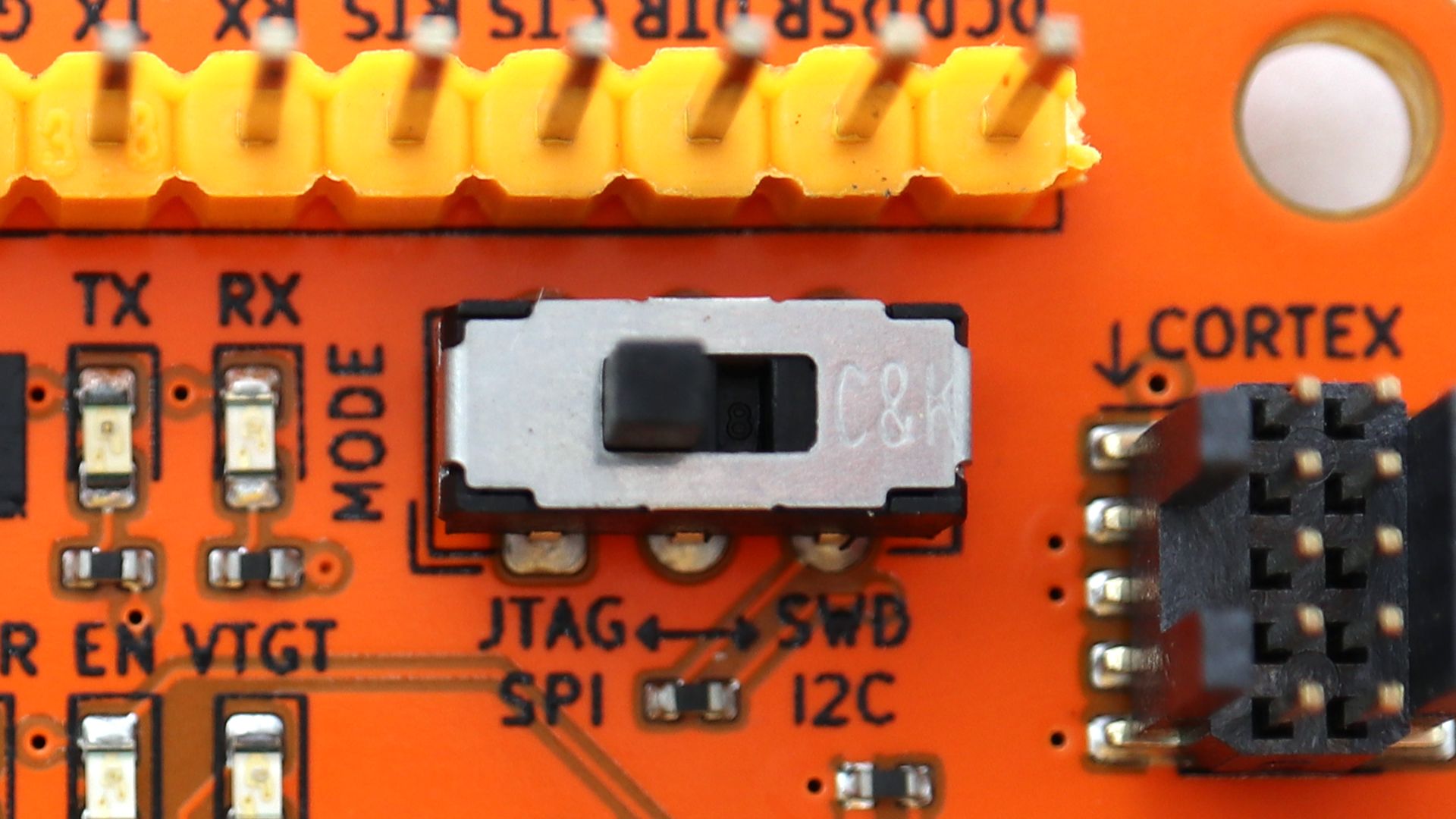
I2C/SWD switch
Finally, after taking all this into consideration, we wired up the switch - who knew a simple DPDT could be so complicated!
Now that we’ve walked through the design of the mode switch - lets take a brief look at how we can use it to prototype and debug speaking with an I2C device: