Project update 7 of 11
The Journey to Funding
by Sid PriceAlmost two years ago, our project to add support for remote, isolated operation to the Black Magic Probe was born. The journey has been challenging at times, but always interesting. Our campaign comes to a close in just over 24 hours, and we thought revisiting that journey might be helpful for those who are still on the fence about backing ctxLink.
The current backer price is the least expensive ctxLink will ever be, so don’t miss this opportunity!
The Mess-of-Wires Stage
Like almost every project, ctxLink began life with evaluation boards and a breadboard.
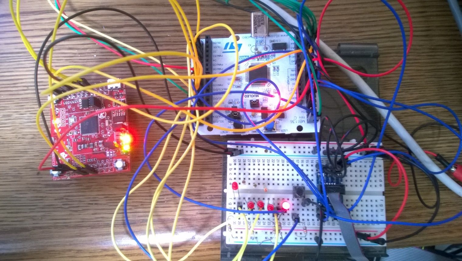
ctxLink is based on the STM32F401RE but the initial prototype – seen above – used a Nucleo-F411RE because that’s what we had on hand. The red board to the left is an evaluation board from Texas Instruments for their CC3100 Wi-Fi module.
The Evolution of ctxLink
As many of you know, breadboards, jumpers, and evaluation boards are great when you want to jumpstart a project, but they introduce a level of instability that can really slow down the development process. Moving to a PCB assembly as soon as possible is the way to go.
Versions 1.2 to 1.4
The photo below shows the first two iterations of the ctxLink PCBs. Observant readers will notice that the Wi-Fi module changed between these two revisions.
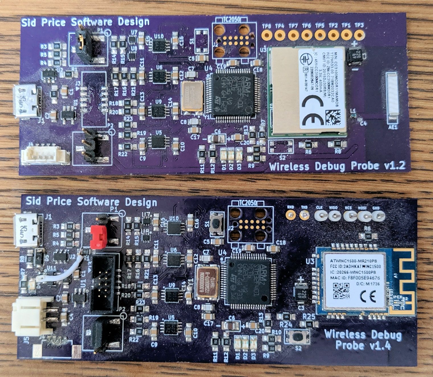
The lower PCB (v1.4) is the first version to use the WINC1500 Wi-Fi module from Microchip. We made this change for a couple of reasons. First, the integrated PCB antenna was attractive. Second, a colleague hand-assembled the PCBs for us, and we had a lot of trouble getting the CC3100 nicely mounted. All of the TI module’s connectors are on the bottom, and the yield on the prototype run put us off using it. To date we have not had issues assembling the WINC1500.
A second major change between the above iterations was the addition of battery support and charge management.
Versions 1.5 & 1.6
ctxLink v1.5 was the first iteration for which we used a Contract Manufacturer.
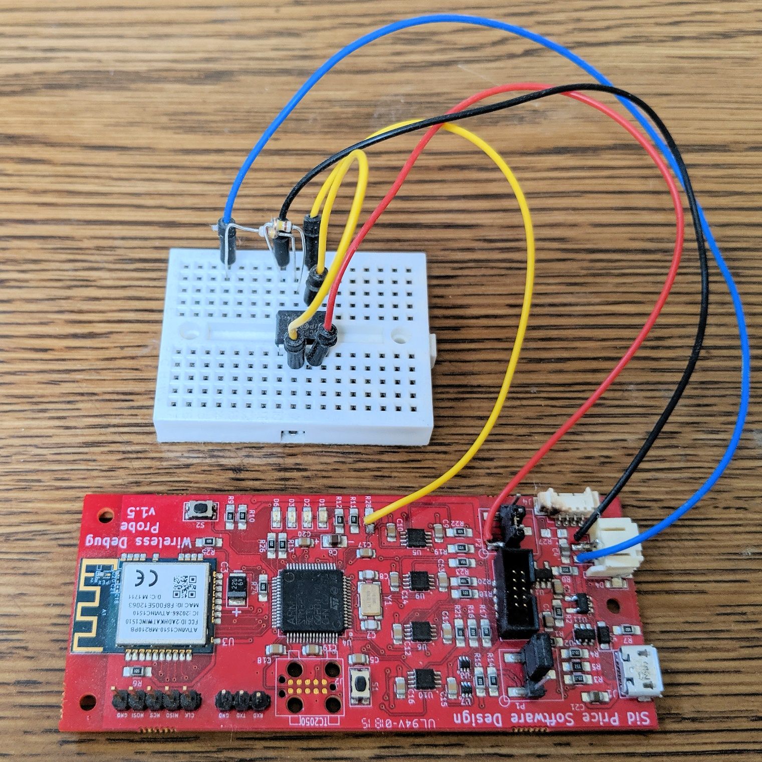
MacroFab produced a short run for us – just two units – and it was our intention to move forward quickly with a production version. That was not to be, however, as we discovered an issue with the MCU’s battery monitoring. Careful study revealed that the load placed on the battery monitoring chip, when no battery was connected, was too high. The chip was failing to detect the absence of the battery. Once again it was time to bring out the breadboard. We inserted a high-impedance buffer between the management chip and the MCU ADC input (used to measure battery voltage), and that did the trick.
With the above change evaluated, v1.6 was sent off to PCBWay for manufacturing. We received the assemblies from PCBWay on time, and all but one worked out-of-the-box.
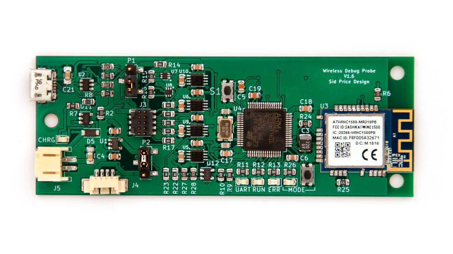
Debugging the one failure revealed the need to make a small Bill of Materials (BOM) change. We had been bitten by a tolerance spread on that one assembly, and the potential divider used to feed the battery voltage to the MCU ADC really needed to use 0.1% resistors.
Between v1.5 and v1.6, we also removed the TAGConnect footprint and the testpoints and added pads on the back of the PCB to interface with the test and programming jig.
Which Brings us to Now
This journey has been long, but it has also been rewarding. Now we’re getting close to the finish line, and the baton is in your hand! We really appreciate the support of our backers, and we have one more favor to ask each of you. Please share your enthusiasm for ctxLink – on social media, in a blog post, amongst your colleagues, at the local hackerspace, or wherever you go to talk about things that excite you – and help us take these last few steps. Thank you!