Project update 3 of 9
Configuring Drive Voltage and Current
In this update, I’ll be discussing how the Wi-Fi Stepper controls the voltage and current of your stepper motor during operation. Having a good understanding of the basics of stepper motors is helpful here and there are plenty of resources available. This post will go over the specifics of the Wi-Fi Stepper and it’s two modes of control: Voltage and Current.
Voltage Control
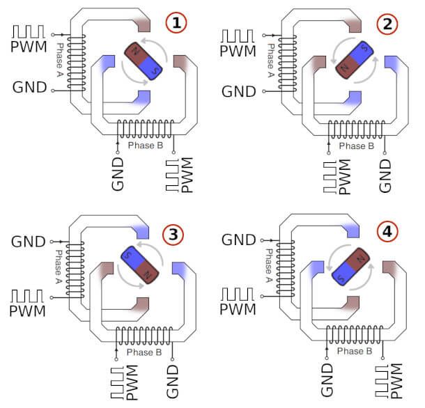
Under Voltage control, the input voltage (Vin) is pulsed to each of the two motor phase coils at a configurable frequency (default 23.4kHz). This is called Pulse-Width Modulation (PWM) and is a way to vary the "effective" voltage on the coils. The Duty Cycle (percent time the voltage is high) determines how much of this effective voltage the phase sees. By alternating the timing and duty cycle of the PWMs on each of the phases, the stepper motor coils are energized accordingly resulting in shaft rotation.
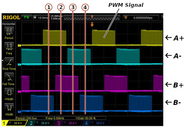
Attaching an oscilloscope and probing the A+, A-, B+, and B- terminal connections (each side of Phase A and Phase B motor coils), we can see the PWM control in action. In this test, we are using 24V input.
KTval Registers
There are four registers to configure voltage/current on the Wi-Fi Stepper. Collectively, they are the KTvals set of registers. When the motor is accelerating, KTaccel is used. Likewise KTdecel is used during deceleration. KTrun and KThold are used when the motor is running at a constant speed and when the motor is stopped but holding position, respectively. Using these four registers, you can define different voltage/current for different phases of your motor’s overall movement. The math behind all KTval registers are the same and as such, we will designate KTval to refer to all four registers identically.
KTval is a floating point number between 0 and 1. Under Voltage control, it sets the maximum duty cycle of the voltage PWM driver (0.1 = 10%, 0.2 = 20%, etc.) Under Current control, it behaves differently and is covered in detail in the Current Control section below. (Note: KTval is named by the STspin motor driver series logic controllers. Under Voltage control, it assumes the Kval configuration, and under Current control, it assumes the Tval configuration.)
It’s a bit hard to make out the PWM waveforms on the oscilloscope capture above. We’ve drawn a simplified diagram to show the point.
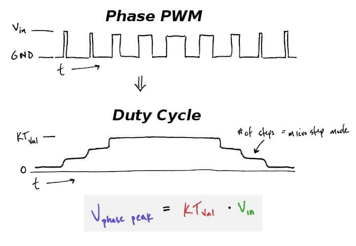
Interpreting the equation, what this means is that the peak PWM ("effective") voltage on the phase coils is the KTval setting multiplied by the input voltage (Vin).
Current Control
Under Current control, a feedback loop is introduced through a current-sense resistor (Rsense). The motor is PWM’d until a desired current is achieved. Because motor torque is proportional to current, using Current mode allows you to directly command torque, independent of speed or motor load.
In this mode, KTval defines the Vsense comparison voltage (0.1 = 100mV, 0.2 = 200mV, etc.) This voltage is directly related to the current through the motor coils by the following equation
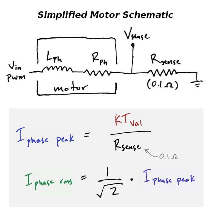
This equation doesn’t depend on input voltage (Vin) or motor phase resistance. What this means is that, regardless of the input voltage or your motor size/type/series resistance, you can directly specify the motor coil current.
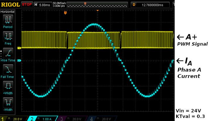
One last picture to show Current mode in action. Below is an oscilloscope capture showing the input PWM along with the measured Phase A coil current. In this test, we’re using KTval of 0.3 which equates to 3 Amps peak current. You can also see the 1/16 microstepping in action.