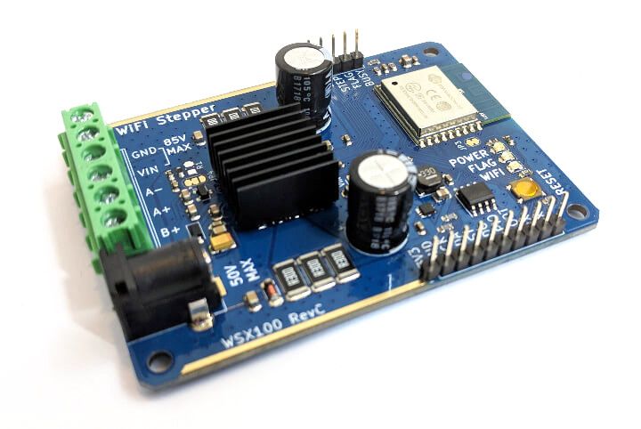
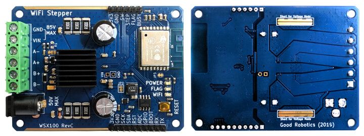
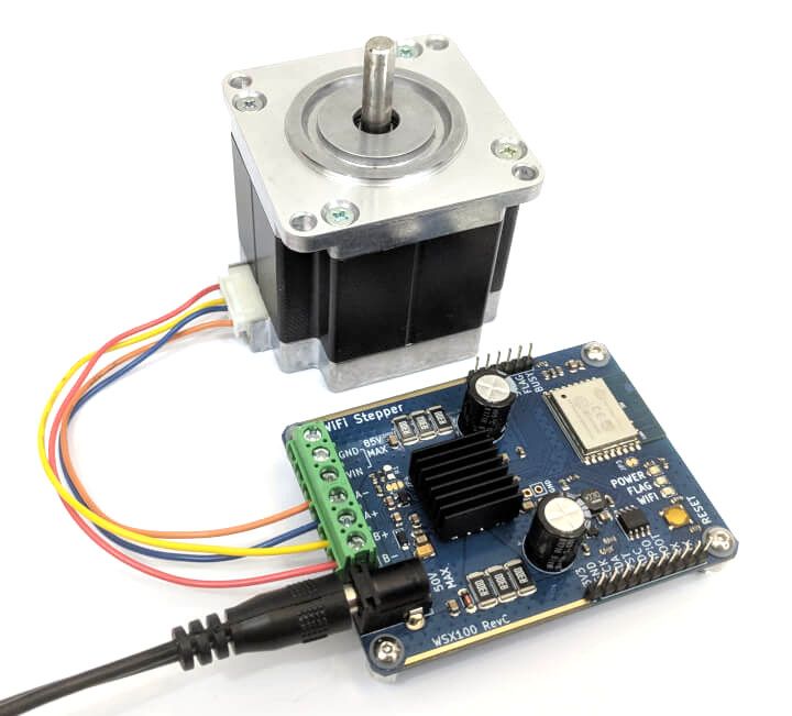
Wi-Fi Stepper is a feature-packed, easy-to-use, stepper motor controller accessible over Wi-Fi. It can handle small to big stepper motors under high current. You can send crypto-secured commands over Wi-Fi from a computer, phone, or any other platform. Integration with other controllers is possible using the step clock and direction input pins. Wi-Fi Stepper makes controlling a stepper motor easy and productive.
Use Wi-Fi Stepper in projects like:
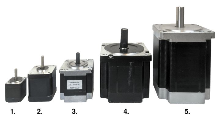
Many projects need a way to interact with the real world. For a lot of applications, stepper motors are the preferred way. They work well at slow to medium speeds and without gearbox reductions. There are plenty of inexpensive NEMA mounts to choose from. They have excellent torque ratings and can even provide high torque at extremely low speed. Stepper motors can run at speed, or as a servo that holds position at any angle. Stepper motors are commonly used in CNC applications and are a great entry-level motor to learn the basics.
With a proper power supply, this project supports most motors on the market. With its voltage and current ratings, even the mammoth NEMA 42 is within its comfort zone for the most demanding applications.
The software side of stepper control is also made easier with Wi-Fi Steppers open source software integration options, including a powerful web application with quickstart functions and guides.
| Wi-Fi Stepper | Tarocco | OpenMYR | uStepper S | |
|---|---|---|---|---|
| Input Voltage | 9-80 V | 36 V | 8-14 V | 8-42 V |
| Output Current | 10 A | 10 A | 2 A | 2 A |
| Step Controller | Included | Needed | Included | Included |
| NEMA Sizes | Any | Any | 17 | 17/23 |
| Open Source Hardware & Software | Yes | Yes | Yes | Yes |
| Development Environment | ESP8266 | N/A | ESP8266 | Arduino |
| Wi-Fi | Yes | No | Yes | No |
| Security | Crypto Chip | N/A | No | N/A |
| Encoder Feedback | No | Yes | No | Yes |
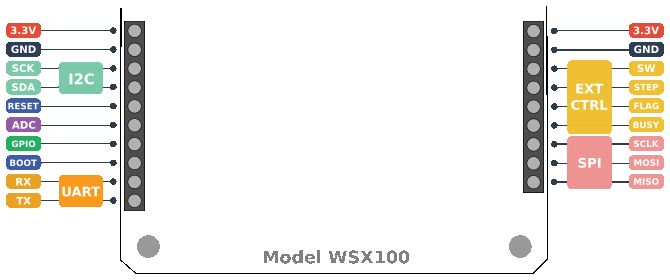
| I/O Expandable | Yes | No | Yes | Yes |
| Cost | $59 USD | $55 USD | $35 USD | ~$53 USD |
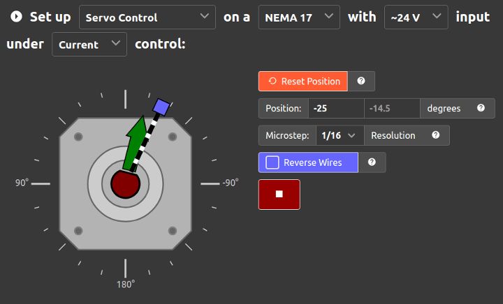
To help you get started, we’ve written a web application that allows you to start moving within minutes of plugging in your motor. You can adjust any configuration setting, test simple motion commands, and generate example code all from the Quickstart dashboard interface.
Drag and edit servo position quickly and intuitively or enter in precise angles. View openloop position feedback and manage step sizes.
Set RPM and visualize speed. Manage hard stop (active bridge) and soft stop (high impedance bridge) settings. Enable stop on switch engagement (for E-Stop or homing).
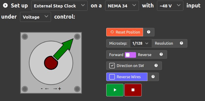
Use an external motion driver to control the motor. Direction configuration can be tied to switch input.
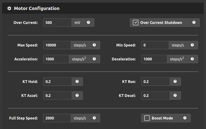
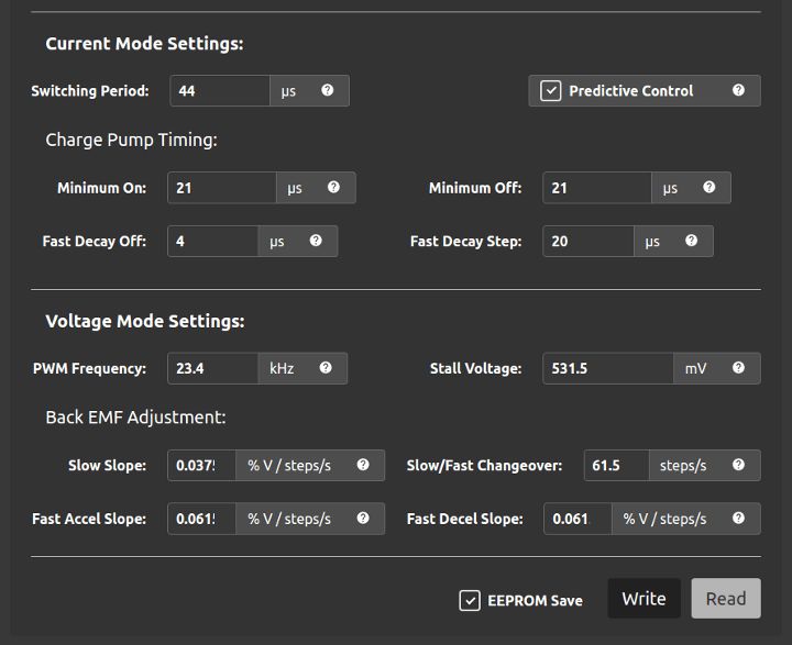
Specify safety limits, speed profiles, torque settings, and speed optimization. With advanced configuration, you can manage current and voltage waveform generation, back EMF compensation, stall detection, and more.
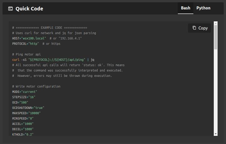
Once you’ve dialed in your motor, generate configuration and motion commands that match the quickstart settings.
We love open source! All of our software, hardware, documentation, everything is MIT license free(dom).

We started this project because we were finding it difficult to drive stepper motors simply and cheaply. We saw an opportunity to help our fellow makers and build a board that incorporates the logic-controller, motor driver, H-Bridges, and provides secure access over Wi-Fi. This all-in-one board can be easily integrated into projects like robotic arms, linear camera sliders, CNC axis additions, automatic pet feeders, security gate openers, and any other project that involves stepper motors.
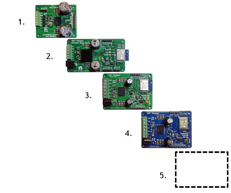
We’ve come a long way from the early prototype days. We developed the first Wi-Fi stepper breakout boards in August 2018. This proved to us that such a board was possible and worth doing. Since then, three more board revisions have refined and proven the design. We’ve tested and tested everything from current capacity of the traces to safety features of the board, and as many different stepper motors as we could throw at it. We’ve tweaked the layout to make it easier to mount, easier to modify, and easier to integrate into larger projects.
We have one more revision in mind. With your support, we’ll cross the finish line with the Rev C production version and send you a great product.
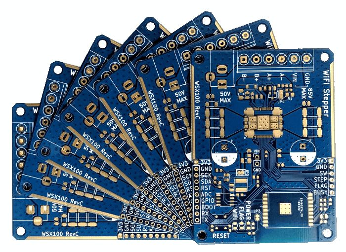
We’ll be monitoring the orders as they come and working with our suppliers to pre-order components as needed. We’ll be using PCBWay for board fabrication and assembly. Once the boards are assembled, we will test and V&V each board throughly before sending them to you.
Most of the technical challenges have already been worked out. A version of the software with all major features is complete. Right now, the team is finishing up the security features, testing the Python library, and adding copious amounts of polish to the user interface and documentation. One more board revision for minor tweaks, IO pin positioning, and DFM (design for manufacturing) is in the works as well.
A possible risk with this project is a logistical one. There are some critical components that the board is designed around (such as the stepper motor controller). We’re working with our suppliers to guarantee a stable supply. As a backstop, we also have an order directly from the manufacturer. This means that we’ll be able to honor our commitments to all our backers, even if our supply chain has issues.
Everything will be shipping from Portland, Oregon, USA using Crowd Supply’s fulfillment services. For more information, see the Crowd Supply Guide on Ordering, Paying, Shipping.
Produced by Good Robotics in Santa Cruz, CA.
Sold and shipped by Crowd Supply.

Thanks for helping make the Wi-Fi Stepper a reality! You will be rewarded with good karma and regular backer updates.

Includes the Wi-Fi Stepper board, NEMA 17 stepper motor, and 24 V power supply packages. Everything you need to get started.

A Wi-Fi Stepper board to control small and large stepper motors.
A 3-pack of the Wi-Fi Steppers - boards only.

Include a 24 V/3.75 A DC power supply that has been tested to work well with NEMA 17 and NEMA 23 motors.

Include a NEMA 17 high torque stepper motor.

Good Robotics develops hardware and embedded software for robotics and control applications. Our focus is on adapting professional-level platforms and techniques for a wider range of users such as makers/hobbiests. We have experts in electrical engineering, embedded systems, mechanical engineering, and sensor fusion/controls.

Everything you need to navigate the world's largest electronics market
Wireless, fully programmable, open source, ESP32 macropad featuring 16 RGB, mechanical, hot-swappable keys and two RGB rotary encoders
The ultimate playground for hardware programming in Swift