Project update 2 of 9
Homing
Using limit switches to home your motor
Wow! In just a few days we’ve reached over 40% of our funding goal! We’re off to a great start, thank you all so much!
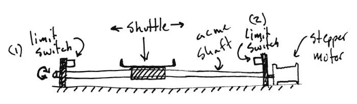
For the first project update, let’s discuss a common topic that a lot of stepper motor projects utilize: using limit switches to find ‘home’ position. In particular, lets consider a linear rail with two limit switches (one at each end) and determine the homing procedure. The setup is as follows: an acme shaft connecting a stepper motor to a shuttle. When the motor turns, the shuttle moves linearly along a track between the two limit switches. The number of turns determines the position of the shuttle along the track.
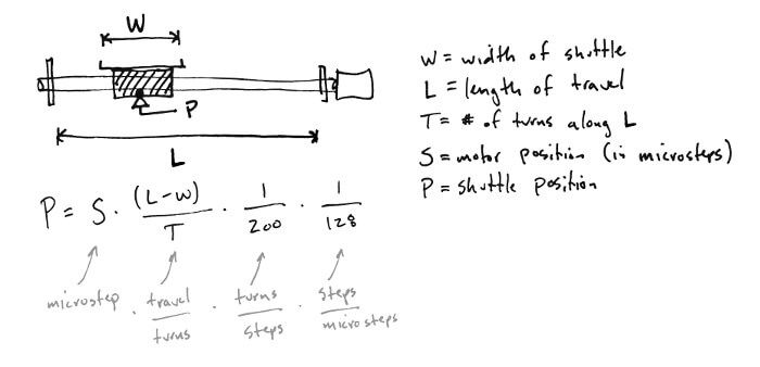
We know the shuttle’s position by keeping track of the number of steps the stepper motor moves. Each step turns the acme screw a little bit, which moves the shuttle along the track a little bit. The following formula describes the relationship between the shuttle position (P) along the track and the current motor microstep (S) ___[Note: this assumes the typical 200 steps per revolution (1.8 degrees per full step) and that the motor is configured to 128 microstep mode]___. (P) is measured in inches (or mm) relative to some starting position. Finding that starting position is what this is all about.
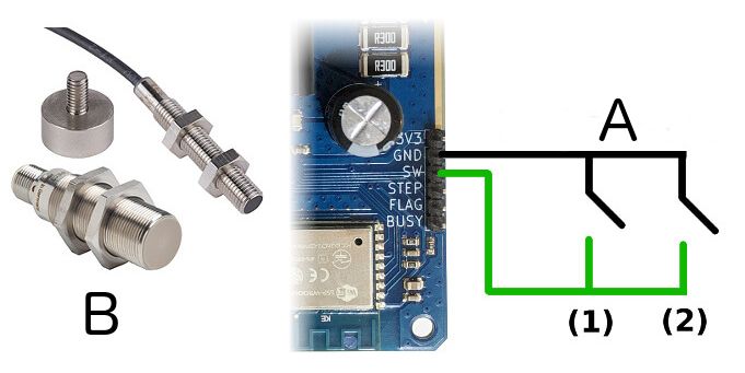
First let’s talk about limit switches though. For this application, I recommend two magnetic proximity sensors (one on each side) connected in parallel between the SW and GND pin as shown in the following diagram. Without a magnet nearby, they are ‘open circuit’. When a they come in proximity with a magnet (strategically mounted on the shuttle), they short, grounding the SW pin. ‘Proximity’ means there is an air gap between the sensor and magnet, which is handy for two reasons. First, there is no mechanical contact, preventing wear and tear from eventually breaking the switch. Second, this extra cushion is advantageous during the homing routine and will give us room to decelerate the motor, preventing electrical spikes and back EMF.
The switch input SW is a handy feature and can be used in a number of ways. It’s connected to pull-up resistor, so grounding the pin triggers the action. In this application, it’s utilized as a limit switch. However, you can configure it to work as an E-Stop or generic switch that’s not tied to any action. When it ___is___ tied to an action, however, the triggering mechanism is built into the motor circuitry. Every 125 nanoseconds, the motor logic checks the switch value and potentially carries out the action, independent from the Wi-Fi stack (and all other logic). This means that it can be relied on to work in safety critical applications.
Back to our example. When powering up the shuttle can be in any position along the length of the track. Start out by sending a speed command with ___stopswitch___ to true. This will drive the motor at a specified speed and stop the motor when the switch triggers (shuttle comes into proximity with the switch). Once this happens, the motor will execute a ‘soft stop’, which uses the configured deceleration slope to spin the motor down. This is where using a proximity sensor and having a little bit of extra air gap cushion comes in handy.
Next, issue a homing command to reverse shuttle direction and move at a slow, minimum speed until the switch is depressed. Once this happens the motor will execute a ‘hard stop’ (stop and hold position with active bridges) immediately. At this point, the motor has accurately found the home position.
Before we locate the second limit switch, lets discuss how the Wi-Fi stepper internally keeps track of it’s position. There are two registers: abspos and mark. They work together and can be used to determine the number of steps between the two limit switches. Abspos and mark are 22-bit signed integers and are used to store the motor’s microstep. Abspos is continually updated with the current value during movement, and mark use user-configurable. During the homing routine when the switch is triggered, mark with automatically be set to the abspos value, and abspos will be set to zero.
To find the limit switch at the other end (and with it, the maximum distance of travel), you want to run through the same routine as we just did, except in the opposite direction. Once you do this, the mark register will hold the number of microsteps between limit switches. Plugging (S) into the formula above, you can determine the maximum value of (P) and the length of travel of your linear slider.
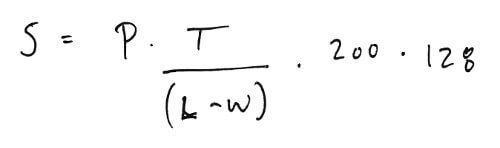
Finally, you can send the shuttle to any position (P) between the limit switches by issuing a servo command with the microstep value (S) computed below. This will move the shuttle to that position (taking into account acceleration and deceleration slopes) and hold the shuttle there by keeping the bridges active.
To recap, this post covered how to use two limit switches to determine the home position and length of travel of a shuttle on a linear rail. The following features were discussed:
- SW switch input hookup
- Speed command
- Homing command
- Minimum speed configuration
- Abspos and mark registers
- Servo command
- Acceleration/Deceleration slopes
Thanks again and I look forward to answering any questions you have!