Piconomix
Microcontroller Boards
Elecrow
PX-HER0 Board
The expert field guide to embedded ARM systems

Funding ended on Apr 09, 2020 at 04:59 PM PDT.
Piconomix
Microcontroller Boards
Elecrow
Funding ended on Apr 09, 2020 at 04:59 PM PDT.
PX-HER0 is a low-power ARM Cortex development board that’s been carefully crafted with embedded education in mind - hardware, software, and documentation. Discover and free your inner embedded hero!
PX-HER0 and its whole ecosystem (open source C library and documentation) are designed to be a hands-on guide to teach people to become embedded pros at their own pace.
The ARM Cortex series is THE processor of choice, but it is hard to master with everyone hiding the mechanics under layers of abstraction and poor documentation. We want to reveal how it works with carefully crafted tutorials, examples, and a well structured and documented C library to create that Eureka! moment of enlightenment.
We tried to document each step of the way concisely to get you up and running as fast as possible, for example:
Also included in the PX-HER0 ecosystem is the CLI Explorer App (Command Line Interpreter) that creates a "Un*x Shell"-like environment running on the PX-HER0 board so that you can easily experiment with GPIO, PWM, ADC, DAC, I²C, SPI, and 1-Wire using only ANSI/VT100 terminal software.
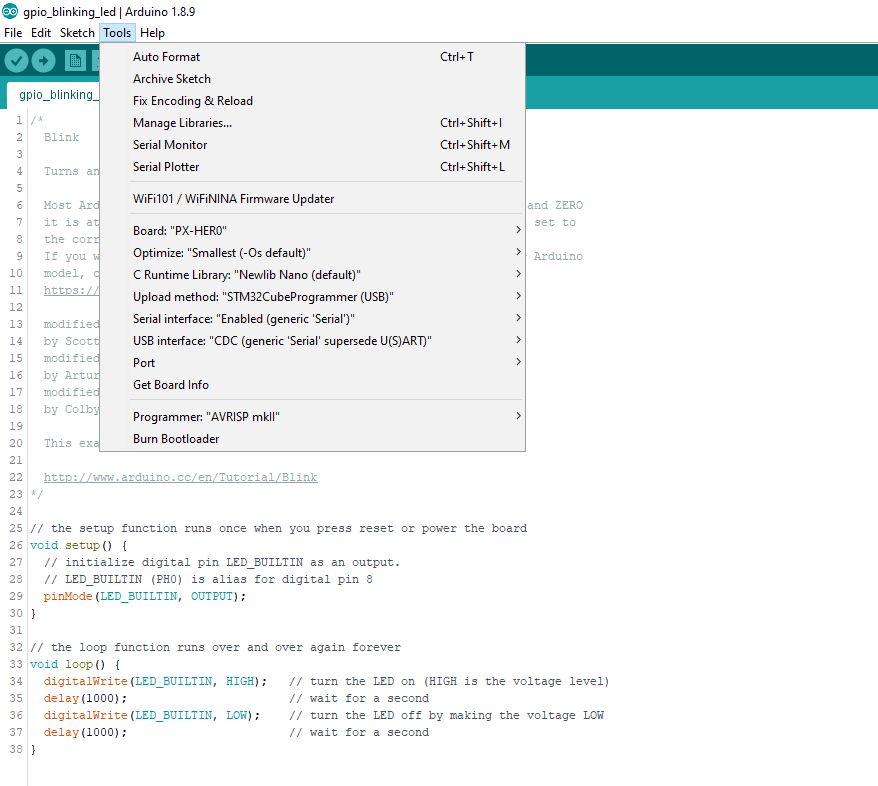
Native support for the PX-HER0 board has been added in Arduino_Core_STM32 version 1.8.0. The set-up steps have been fully documented. Also included are several PX-HER0 specific EXAMPLES
The C library is MIT licensed and available on GitHub.
Most OSHW designs hide some of their "magic sauce". The schematics are hard to follow and complete manufacturer part numbers are not disclosed. PX-HERO lowers the barrier in terms of design openness… judge for yourself:
A quick "double-tap" of the RESET button activates the bootloader and a mass storage drive called "HERO-BOOT" appears. Then it is an easy drag & drop operation to copy the new UF2 formatted file to the drive.
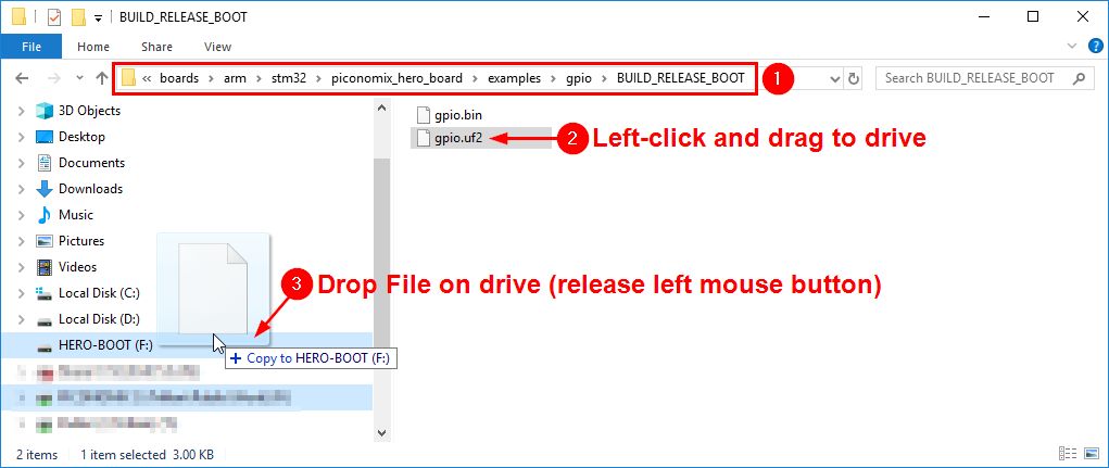
The STM32 ROM bootloader can also be activated by using the BOOT jumper and STM32CubeProgrammer GUI software.
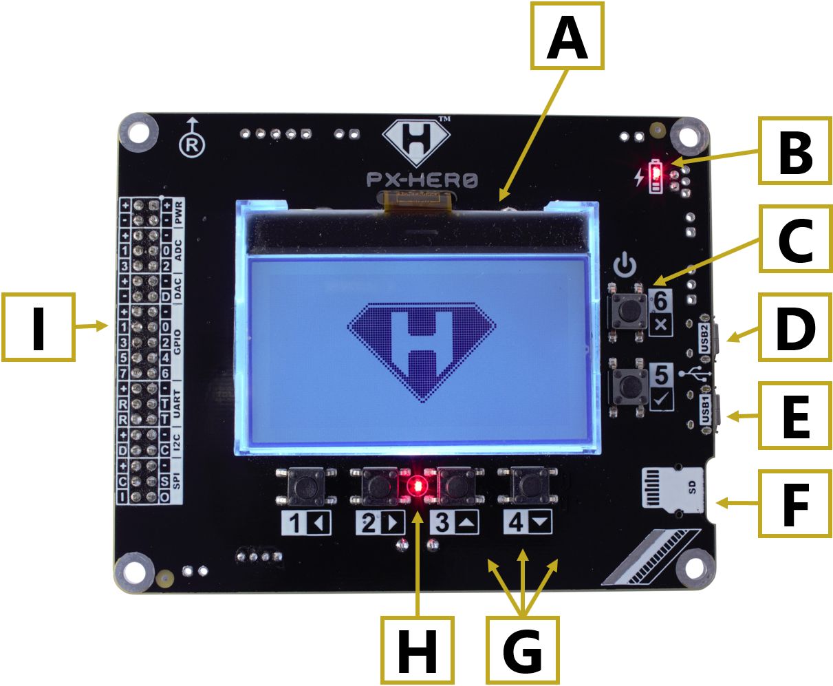
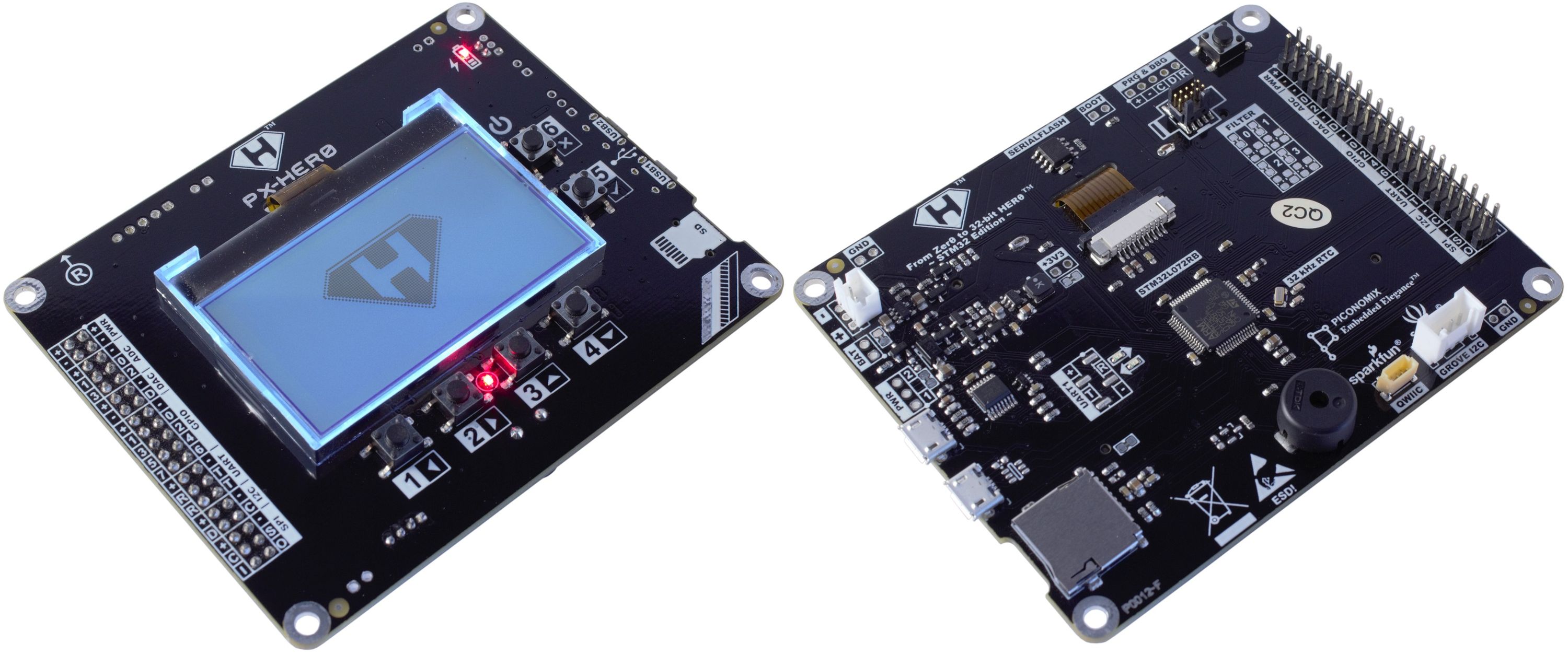
| PX-HER0 Board (Top) | |
|---|---|
| A. 128 x 64 Graphic LCD with backlight | F. microSD Card Slot |
| B. Charger LED | G. User Buttons |
| C. User/Power Button | H. User LED |
| D. USB2: USB-Serial Bridge | I. Peripheral Connector* |
| E. USB1: STM32 |
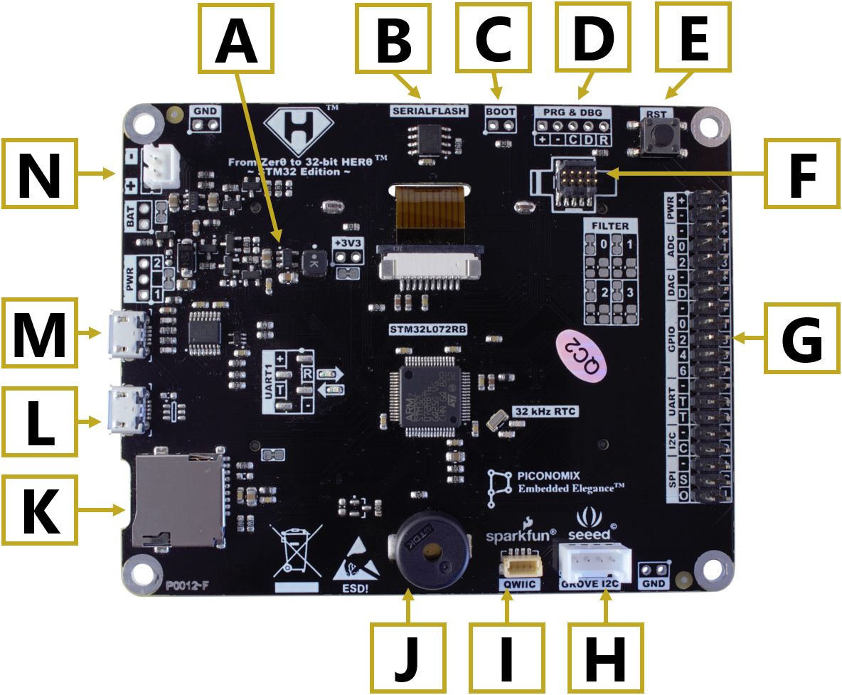
| PX-HER0 Board (Bottom) | |
|---|---|
| A. +3V3 Step-down DC-DC Regulator | H. Seeed GROVE I²C* |
| B. Serial Flash | I. Sparkfun Qwiic / STEMMA QT I²C |
| C. BOOT selection | J. Piezo Buzzer |
| D. Prog & Debug Connector | K. microSD Card Slot |
| E. Reset Button | L. USB1: STM32 |
| F. ARM Cortex Debug Connector | M. USB2: USB-Serial Bridge |
| G. Peripheral Connector* | N. Li-Po Battery Connector* |
The three through-hole parts (Seeed GROVE, Li-Po Battery and Peripheral Connector) are supplied separately with the board to provide flexible choices.
There isn’t a uniform standard for the positive and negative terminal of a Li-Po battery and the vertical through-hole JST connector can be rotated 180º to cater for both permutations. The dual PCB footprint also allow a 3-pin Molex connector to be mounted.
Similarly, the 40-pin vertical peripheral connector can be mounted on the bottom or the top side. It can also be swapped for a longer, right-angle or female header.
Each set of peripheral pins are logically grouped and labelled with their own ground and power connections making it effortless to interface with other devices or components.
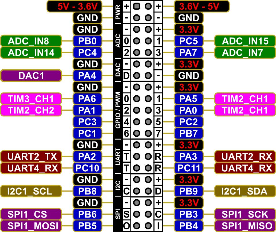
By grouping the pins together it is also possible to plug in a 40-pin IDC ribbon cable and the multiple GND pins preserve signal integrity.
The STLINK-V3MINI is a low cost, high performance in-circuit debugger and programmer for STM32, and is available to order with your PX-HER0 board.
Liberal serial debug output (printf) is great for tracking the general flow of your program to get a helicopter overview, but for fine resolution, insightful view, you need a good in-circuit debugger to halt and single-step the processor and to inspect the peripheral registers and memory content (see HERE). It really is the best coding teacher and you would be flying blind without it.
Unfortunately an on-board debugger will increase the board’s power consumption and that’s why we decided to offer it as a separate easy-to-connect-and-disconnect item so that you can have all the advantages, but none of the disadvantages.
The 10-pin open polarized connector is very expensive ($1.50 on Adafruit; $3.60 on Digi-Key), but we did not want to compromise a great out-of-the-box debugging experience so we included it on the board. It prevents wrong-way-around or off-by-one connections. It can accept the Segger J-Link EDU Mini and the open sides also allow it to accept the extended 14-pin connector of the low cost, high performance STLINK-V3MINI.
The open sides also allow you to grip the sides of the connector with your fingers to pull it out gently and not yank it out with the ribbon cable.
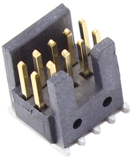

Left: ARM Cortex Debug Connector; Right: STLINK-V3MINI
A rock-solid FTDI FT230XS USB-serial bridge that just works on Windows, Mac, and Linux is connected to UART1 of the STM32. This provides an easy serial communication facility without having to struggle with the complexity of a USB firmware stack. It can be used for "fire & forget" debug output or a small XMODEM-CRC bootloader
Debugging firmware on a microcontroller while it is executing a USB device stack is not easy. The PC (USB host) is continuously polling the microcontroller (USB device). USB communication is interrupted as soon as the processor is halted with a debugger and the PC will assume that the device has been disconnected. That’s why it is better to pipe debug output over UART and not USB.
The PX-HER0 board has been designed from the ground up with low power consumption in mind to operate for months or years on a single battery charge.
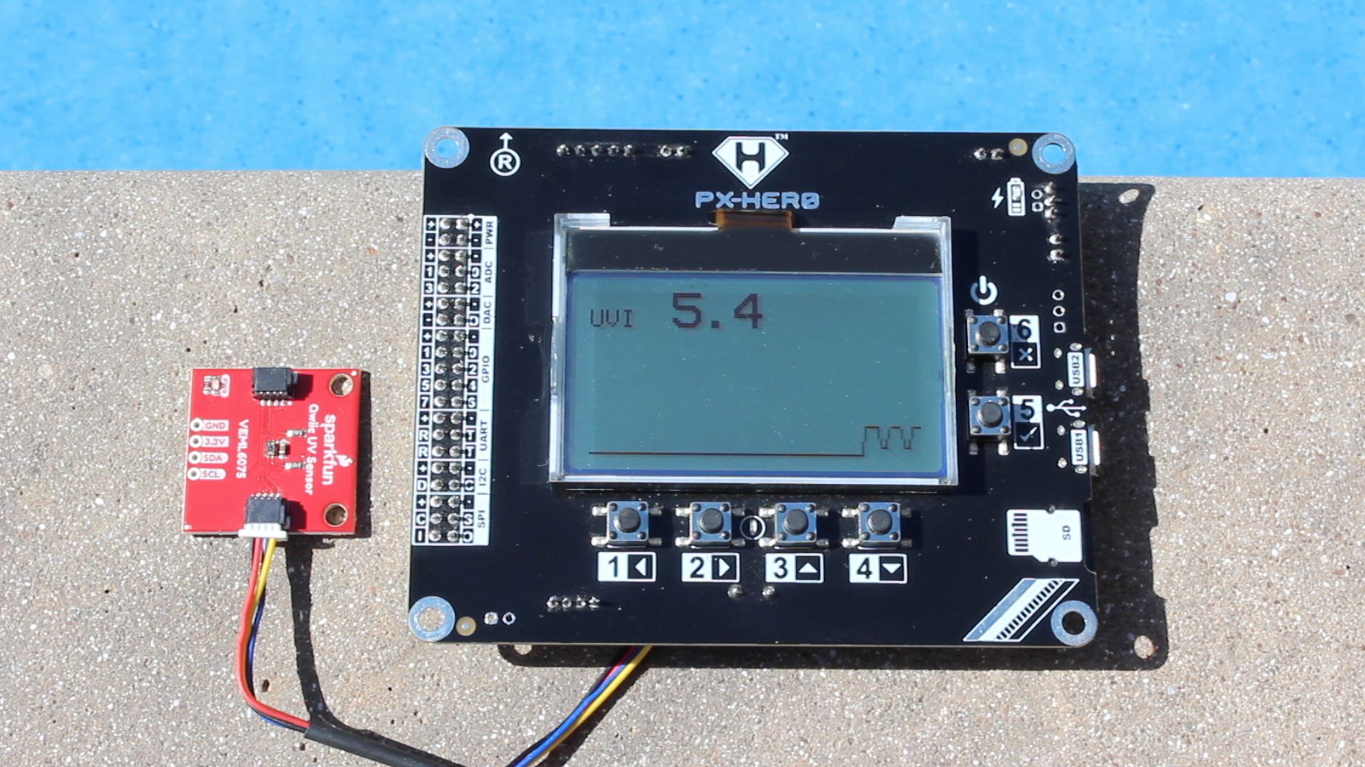
A not so obvious advantage of the large monochrome LCD is the fact that it is clearly visible in direct sunlight. The display consumes a minuscule 150 µA with an active display and 8 µA when powered down. The backlight consumes only 1.1 mA when enabled.
The STM32L072RB is a member of the special Low Power Cortex-M0+ ARM series and consumes only 6.65 mA when executing at 32 MHz. It consumes a paltry 1.6 µA in STOP mode while maintaining an external 32.768 kHz crystal source for its Real-Time Clock. A resistive divider circuit can be used to detect when USB is disconnected and power down the USB interface.
The TI LM3670 step-down DC-DC regulator was selected as the best compromise between maximum output current (350 mA @ 95% efficiency) and no-load quiescent current (15 µA), while still having a developer friendly SOT23-6 SMD footprint. The micro is able to measure the battery voltage using a zero burden resistive voltage divider and switch off the power supply when too low. It’s an insignificant 0.1 µA when shut down.
A Diodes DMP2305U P-channel MOSFET with an on-resistance less than 0.06 Ohm is used as an ideal diode circuit to supply power to the board from the battery.
The Adesto AT25SF041 serial flash memory is great for low power IoT data logging and consumes only 2 µA when put into deep power-down mode.
The FTDI FT230XS USB-Serial bridge consumes 125 µA when USB is disconnected so it is powered separately from USB +5 V while an NXP 74LVC1G125GW buffer is used to isolate the serial interface and block parasitic current (consuming only 1 µA in the process).
A comprehensive Low Power STOP Mode Example is provided that demonstrates that the WHOLE system draws 24 µA from the battery @ 3.6 V with the display off and 170 µA with the display on.
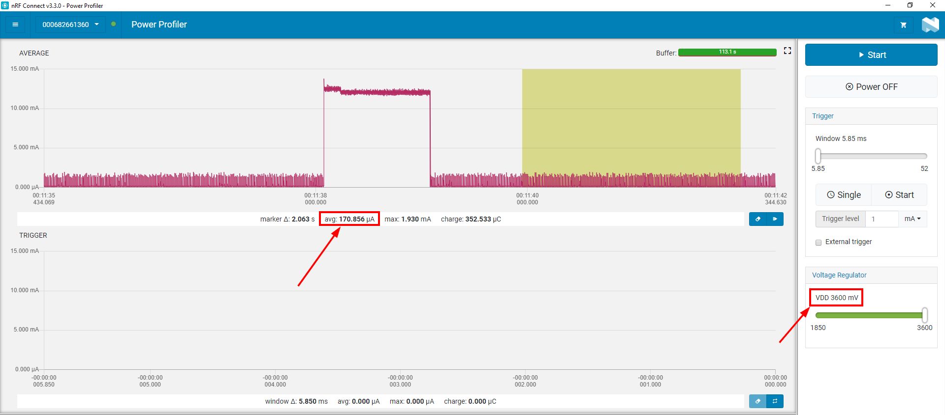
Measured using a Nordic Power Profiler Kit.
The PX-HER0 board will be manufactured by Elecrow, an established manufacturer in Shenzhen, China using a meticulously documented data pack. Two revisions of prototypes have been manufactured to ensure that component sourcing, manufacturing, programming, and testing will go smoothly. A comprehensive test plan with test software has been created and trailed to assure the quality of each board.
All orders will be shipped to our customers using Crowd Supply’s fulfillment services. Once manufacturing is complete, we’ll make a bulk shipment to Crowd Supply and, from there, the packages will be shipped out to our individual backers. For more information, you can refer to this useful guide to ordering, paying, and shipping.
Backers can confirm and update their order details and more in their Crowd Supply account.
As with any manufacturing project, there is the possibility of delays, especially with the recent Chinese New Year holiday and the ongoing impact of the COVID-19 Coronavirus in China and beyond. This virus has already disrupted countless lives as well as global supply chains, and it’s something to be mindful of.
All we can promise is that any delays or problems will be communicated clearly with backers through regular updates. We’ll be checking with our manufacturer and delivery service for any news on the developing situation. Although we’ve estimated a longer delivery time to account for the uncertainty, the PX-HER0 delivery date is liable to change. We appreciate your patience and understanding. You can learn more about how you are protected as a Crowd Supply backer in the Crowd Supply Guide.
Having said that, we have taken steps to mitigate production risk:
"Built around ST Micro's popular STM32, Piconomix's board targets everyone from embedded development students to badge builders."
"Pensada para su uso en el sector educativo, esta placa de desarrollo ARM de bajo consumo es compatible con el entorno de desarrollo de Arduino."
"Since it’s supposed to be a way to become more proficient in the platform, [Pieter] has gone through great lengths to make sure that all the hardware, software, and documentation are easily accessible."
Produced by Piconomix in Cape Town, South Africa.
Sold and shipped by Crowd Supply.

One PX-HER0 board.
Want to buy this item? Check the current project page for the latest information.

From the Crowd Supply Basics project.
A tiny, standalone debugging and programming probe by ST for STM32 microcontrollers. The JTAG/SWD interfaces can communicate with any target STM32 microcontroller. A virtual COM port interface allows the host PC to communicate with the target microcontroller through one UART. STDC14-to-STDC14 flat cable included. USB Type-C cable not included.
Want to buy this item? Check the current project page for the latest information.

One PX-HER0 board with STLINK-V3MINI debugger included.
Want to buy this item? Check the current project page for the latest information.
Cape Town, South Africa
PICONOMIX was formed out of my desire to share knowledge, expertise and tools with our open community of engineers, scientists and makers.


