Vesperix Corporation
Software Defined Radio
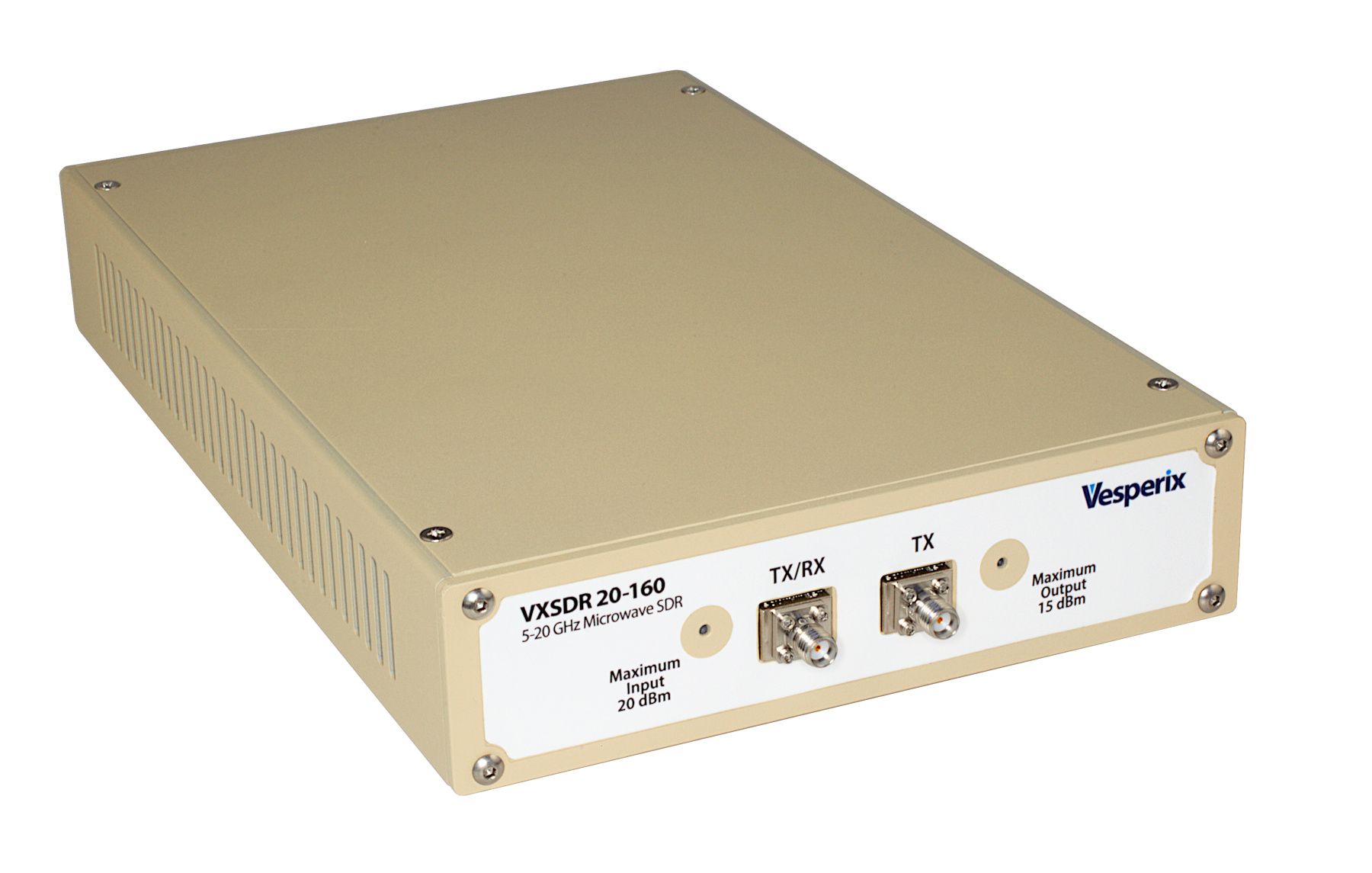
VXSDR-20-160
A high-performance software defined radio covering 5-20 GHz
Vesperix Corporation
Software Defined Radio
The VXSDR 20-160 is a microwave software-defined radio (SDR) that transmits and receives from 5 to 20 GHz at 160 million samples per second. Its capabilities are similar to other high-end SDRs: 10 gigabit Ethernet, support for C++ and Python interfacing, external 10 MHz and PPS inputs, and external local oscillators for precise synchronization.
Software-defined radios have become an important general-purpose tool for researchers, scientists, and engineers, but they rarely cover frequencies above 6 GHz (with a few very expensive exceptions). The VXSDR 20-160 is designed to be used like any other high-performance SDR. With support for simultaneous transmission and reception at a full 160 MSPS, it is appropriate for bench and laboratory use over its full frequency range and is usable at up to 22 GHz. In addition, we’ve designed the host API to simplify porting from other widely used SDR APIs.
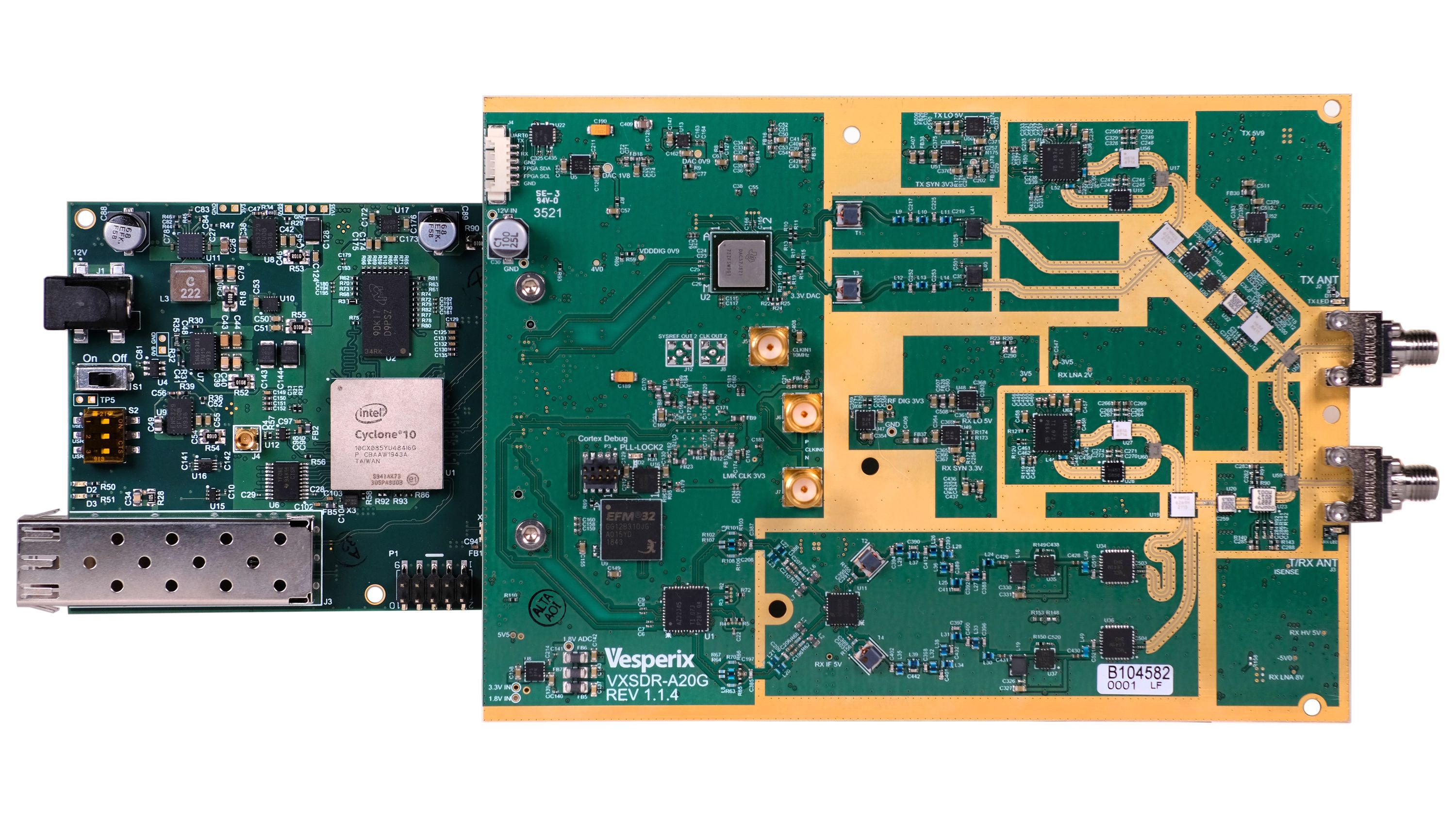
A block diagram of the VXSDR 20-160 is shown below. It includes all major components in the radio and indicates how RF and IF signals, clocks, and control signals are routed within the device.

The radio is made up of two boards: the FPGA at the far right is on the digital board, and all the other components shown are on the analog board. This split separates the RF section and the converters from any network interface so we can change either board and still interface with the other one. In VXSDR 20-600, for example, we have converters running at 600 MSPS on the analog board and a larger, footprint-compatible Arria 10 FPGA on the digital board.
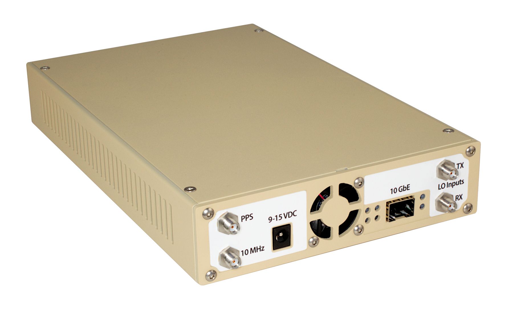
All connections to the VXSDR 20-160 are on the front and back panels. One side has the power and network connections, the other the RF connections.
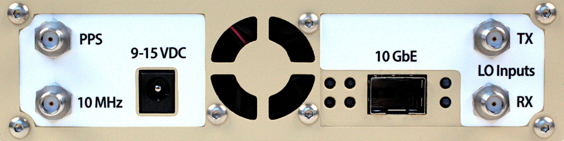
The network side of the VXSDR 20-160 is shown above. Starting from the left, you can see the SMA connectors for the pulse-per-second (PPS) and 10 MHz inputs used to synchronize the radio with external time and frequency references. If the external 10 MHz is not connected, the radio will use its internal reference instead.
The PPS and 10 MHz inputs are 50 Ohm terminated. The PPS input is 3.3 V logic level and 5 V tolerant. The minimum level for the 10 MHz input is 0 dBm, and the maximum is 10 dBm.
Next to these is the power input, which is 9 - 15 Volts DC with a maximum current of 4 Amps. The cooling fan intake is in the center of the network panel. To the right are four system status LEDs, which are documented in the manual.
The SFP+ connector for 10 gigabit Ethernet provides an optical network connection. If you need a copper, 10GBase-T interface, you can use an SFP+-to-RJ45 converter. There are network link-status indicators next to the network interface.
On the far right are the external local oscillator (LO) inputs for the transmitter and receiver. These are used in phased array applications where multiple VXSDR 20-160s must operate coherently. The LO inputs must be offset by 160 MHz below the desired carrier frequency, and must be between 2 dBm and 10 dBm.
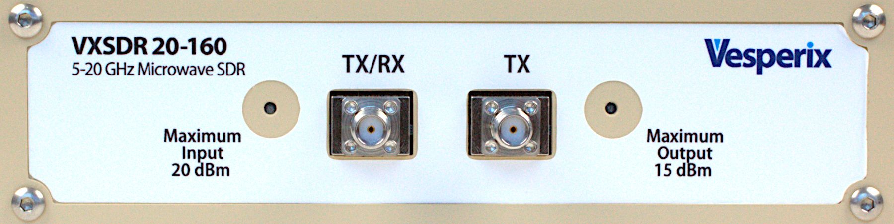
The RF side of the radio shown above accommodates the RF connections and two status LEDs. From the left, the RX status LED is steadily illuminated when the system is receiving. The TX/RX SMA connection can be used for both reception and transmission (though not simultaneously, of course) when the TX output is switched to this port.
The GaN input amplifier is very tolerant of high power inputs. At maximum gain, the input third order intercept (IIP3) of the receiver is approximately 0 dBm, and the receiver can survive inputs at the TX/RX port of up to 20 dBm. While input powers up to 20 dBm won’t damage the radio, you should always adjust the receive gain so that the input power is at least 20 dB less than the IIP3.
The SMA connector for the default TX output is next on the right. Depending on your transmit gain settings, this may output powers of up to 15 dBm, so you must ensure that any devices connected to this port can tolerate the output from VXSDR 20-160. Adjacent to this on the far right is the TX status LED, which is steadily illuminated when the system is transmitting. Transmitting into an unterminated port at high power may damage the transmit section of the radio. For all transmit ports (TX/RX or TX), you should always ensure that the port is connected to a load (another device, an antenna, or a 50 Ohm terminator) whenever you are transmitting.
Both the TX/RX and TX ports use field-replaceable SMA connectors. This allows you to replace damaged connectors without desoldering or swap out one type of connector for another (a plug instead of a socket, for example, or a 2.4 mm connector).
The VXSDR 20-160 is designed for good sensitivity across the entire 5 - 20 GHz operating range. It uses a Gallium Nitride (GaN) low-noise amplifier, which is very robust and reduces the potential for damage from high input levels. The receive noise figure of VXSDR 20-160 is shown below.

On transmit, the VXSDR 20-160 can produce levels suitable for a range of bench-top uses and can drive higher power amplifiers when that is needed. The output power level is shown below.

Although there are many software-defined radios on the market, including a few that can reach 20 GHz, we’re not aware of any direct equivalents to VXSDR 20-160. The table below compares the VXSDR 20-160 to two similar devices.
| VXSDR 20-160 | Signal Hound SM200C | Ettus N320 | |
|---|---|---|---|
| Function | Software Defined Radio | Spectrum Analyzer | Software Defined Radio |
| Frequency | 5 - 20 GHz | 0.1 MHz - 20 GHz | 3 MHz - 6 GHz |
| TX Channels | 1 | 0 | 2 |
| RX Channels | 1 | 1 | 2 |
| Sample Rate | 160 MSPS | 160 MSPS | 200 MSPS |
| Network | 10 GbE SFP+ | 10 GbE SFP+ | 2 x 10 GbE SFP+ |
| PPS & 10 MHz Sync | yes | yes | yes |
| External LO inputs | yes | no | yes |
| Languages Supported | C++, Python | C++, Python, Matlab | C++, Python, Matlab |
| Published API | yes | yes | yes |
| Open Source API | yes | no | yes |
| Dimensions (in) | 10.5 x 6.0 x 1.8 | 10.2 x 7.2 x 2.2 | 14.1 x 8.3 x 1.7 |
| Dimensions (cm) | 26 x 15 x 4.5 | 26 x 18 x 5.5 | 36 x 21 x 4.4 |
| Power Input | 9 - 15 V | 9 - 16 V | 12 V |
| Maximum Power | 35 W | 30 W | 70 W |
| Price | $16,915 | $20,550 | $20,232 |
As mentioned above, our open source host library is available on GitHub. API documentation and build instructions are available on our ReadTheDocs pages. For any questions not covered by the documentation, we are available via email at support@vesperix.io.
This will be the third batch of VXSDRs we’ve built. Our previous batches were for design checkout, internal use, or R&D projects that required variations on this design. We intend to follow the same manufacturing plan for this batch.
Our PCBs are fabricated and assembled by contract manufacturers with whom we’ve worked in the past. Our enclosures are built by third-party manufacturers as well. We attach the RF connectors, install both boards (the analog board, with all the RF components and converters, and the digital board, which hosts the FPGA and the network interface) into the enclosure, burn the firmware for the FPGA and MCU, and test the final product.
Our checkout process includes functional testing as well as measurements of the noise figure, sensitivity, and output power across the full 5 - 20 GHz frequency range. For the initial campaign orders through Crowd Supply, we’ll deliver graphs of these measurements for each individual radio, so you’ll know the precise measured performance of your radio when you receive it.
Once we’re done with manufacturing, final assembly, and testing, we will package everything up and send it along to Crowd Supply’s fulfillment partner, Mouser Electronics, who will handle distribution to backers worldwide. You can learn more about Crowd Supply’s fulfillment service under Ordering, Paying, and Shipping in their guide.
In previous batches, we’ve seen occasional issues at two steps in the manufacturing process. First, although the Covid-related supply-chain mess is mostly behind us, it’s still possible that we’ll have to wait for parts, especially some of the low-volume microwave parts that are not stocked in large quantities by distributors. Second, if our PCB assembly partner has issues placing a component, that board will be reworked to get the assembly correct.
The last step where we could see delays is in the testing process. We have FCC and CE tests to complete, and, although we’re confident the system can meet these requirements, we may have to modify the enclosure or the RF shield on the analog board. We plan to complete these tests on the pilot systems, which are being built now, so we can make any necessary modifications before we start our first production batch.
Produced by Vesperix Corporation in Falls Church, Virginia, USA.
Sold and shipped by Crowd Supply.

Microwave software-defined radio. Comes with a 12-VDC power supply, an instruction booklet, and a device-specific measurement report

Small business doing R&D in communications, sensing, and navigation.